CA 02509440 2005-06-08
TRACK ASSEMBLY FOR AN ALL-TERRAIN VEHICLE
CROSS-REFERENCE TO RELATED APPLICATIONS[0001] This application claims priority under 35USC~119(e) of U.S. provisional
patent
application 60/577,924, filed on June 9, 2004, the specification of which is
hereby
incorporated by reference.
BACKGROUND OF THE INVENTION
1 ) Field of the Invention
(0002] The present invention relates to all-terrain vehicles and, more
particularly to
track assemblies for all-terrain vehicles.
2) Description of the Prior Art
[0003] Traditionally, two types of all-terrain vehicles are proposed either
the wheeled
type or the tracked type. Wheeled vehicles are usually more maneuverable than
tracked vehicles but are not as efficient on uneven or soft terrain such as
snow.
[0004] Mainly two types of track systems have been proposed. US Patent
No. 6,006,847 describes an endless track structure having a substantially
triangular
shape. An endless track belt is mounted over front and rear idler wheels and
two
spaced apart driving wheels mounted on the existing wheel hub of the vehicle.
The
idler wheels are located below the driving wheels and are interconnected with
sliding
shoes. The track belt of US Patent No. 6,006,847 has a wide supporting
footprint.
US Patent application No. 10/165,707 describes an endless track structure
having
also a substantially triangular shape wherein an endless track belt is mounted
over
front and rear idler wheels a driving wheel mounted on the existing wheel hub
of the
vehicle. However, the idler wheels are located above the driving wheel and
therefore
the track belt has a punctualized localized surface with the ground.
[0005] The track structure of US Patent No. 6,006,847 gives better performance
when the vehicle is in deep snow conditions than the track structure of US
Patent
application No. 10/165,707. However, the performance of US Patent No.
6,006,847
CA 02509440 2005-06-08
decreases when the ground surface is harder. Moreover, since it includes
sliding
shoes, it can only be used in snow conditions. Since the track structure of US
Patent
application No. 10/165,707 does not have sliding shoes, it can be used on any
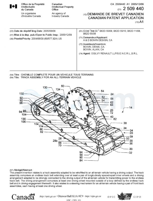
ground surfaces.[0006] There is therefore a need for a new track assembly for an all-terrain
vehicle
that gives as good performance as the track system of US Patent No. 6,006,847
in
snow conditions and can be used on any ground surface.
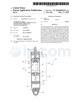
SUMMARY OF THE INVENTION
[0007] An object of the present invention is therefore to provide improved
track
assemblies for an all-terrain vehicle.
[0008] According to one aspect of the present invention, there is provided a
straddle-
type vehicle including at least one track assembly to support vehicle onto a
ground
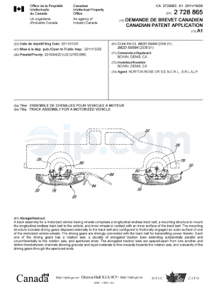
surface. The at least one track assembly comprises a longitudinal endless
track belt
having an outer surface and an inner surface; a frame to mount the
longitudinal
endless track belt to the vehicle; at least one driving wheel disposed
externally to the
longitudinal endless track belt, the at least one driving wheel being in
driving
engagement with the longitudinal endless track belt; and at least two inner
wheels in
contact with the inner surface of the longitudinal endless track belt.
[0009] According to another aspect of the present invention, there is provided
a track
assembly for an all-terrain vehicle. The track assembly comprises a
longitudinal
endless track belt having an outer surface and an inner surface and a mounting
structure to mount the longitudinal endless track belt to the vehicle. The
mounting
structure includes at least one driving wheel disposed externally to the
longitudinal
endless track belt, the at least one driving wheel being in driving engagement
with
the longitudinal endless track belt, and at least two inner wheels in contact
with the
inner surface of the longitudinal endless track belt.
[0010] According to a further aspect of the present invention, there is
provided a
mechanism for facilitating the steering of an all-terrain vehicle having a
pair of track
assemblies. Each track assembly has at least one driving wheel. The mechanism
OR File No. 16902-5CA – 2 –
CA 02509440 2005-06-08
comprises at least one first and second braking systems operatively connected
to
respective driving wheels of the pair of track assemblies; the first and
second braking
systems being independently actuable, whereby upon activating one of the first
and
second braking systems, the driving wheel operatively associated with the
actuated
braking system is slowed down to facilitate turning of the vehicle in the
direction of
the slowed down driving wheel.
[0011] According to another aspect of the present invention, there is provided
an all-
terrain vehicle including a steering mechanism and a pair of front track
assemblies.
Each of the track assemblies comprises at least one driving wheel and at least
one
independent braking system operatively connected to the at least one driving
wheel;
the braking systems of the track assemblies being selectively independently
actuable, whereby upon actuating one of the braking system, the driving wheel
operatively associated with the actuated braking system slows down allowing
the
vehicle to turn in the direction of the slowed down driving wheel.
[0012] According to another aspect of the present invention, there is provided
a
method to facilitate the steering of an all-terrain vehicle having a pair of
front track
assemblies, each having at least one driving wheel. The method comprises
providing
at least first and second braking systems; operatively connecting the first
and second
braking systems to respective ones of the track assemblies; and providing
independent control of the first and second braking systems.
[0013] According to another aspect of the present invention, there is provided
a
method to facilitate the steering of an all-terrain vehicle having a pair of
left and right
track assemblies. The left and right track assemblies respectively includes
left and
right driving wheels and left and right brakes. The method comprises the step
of
providing independent control of the left and right brakes, whereby upon
independently actuating one of the left and right brakes, only the driving
wheel
associated to the actuated brake is slowed down creating a speed differential
between the left and right track assemblies to facilitate steering of the
vehicle in the
direction of the slowed down driving wheel.
[0014] According to a still another aspect of the present invention, there is
provided a
track assembly adapted to be retrofitted to a straddle type vehicle having a
driving
OR File No. 16902-5CA – 3 –
CA 02509440 2005-06-08
output. The track assembly comprises an endless track belt extending over at
least a
pair of longitudinally spaced-apart inner wheels, and a driving arrangement
adapted
to be drivingly connected to the driving output of the straddle type vehicle
for
transmitting power to the endless track belt, wherein the driving arrangement
comprises at least one driving wheel mounted outside of a loop defined by the
endless track belt and in driving engagement therewith.
BRIEF DESCRIPTION OF THE DRAWINGS
[0015] Further features and advantages of the present invention will become
apparent from the following detailed description, taken in combination with
the
appended drawings, in which:
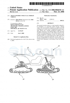
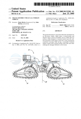
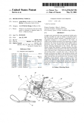
[0016] Fig. 1. is a side elevation view of an all-terrain vehicle provided
with track
assemblies according to a preferred embodiment of the present invention;
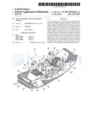
[0017] Fig. 2 is a photograph of an inside perspective view of a mounting
structure
according to the present invention, with a longitudinal endless track belt
mounted
thereon and wherein the mounting structure is mounted on an all-terrain
vehicle;
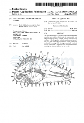
[0018] Fig. 3 is an outside perspective view of the mounting structure
according to
the present invention, without the track belt;
[0019] Fig. 4 is an enlarged outside perspective view of the mounting
structure
according to the present invention, without the track belt;
[0020] Fig. 5 is an inside perspective view of the mounting structure
according to the
present invention, without the track belt;
[0021] Fig. 6 is a top plan view of the mounting structure according to the
present
invention, without the track belt;
[0022] Fig. 7 is a photograph of a front elevation view of the mounting
structure
according to the present invention, with the track belt mounted thereon and
wherein
the mounting structure is mounted on an all-terrain vehicle; and
OR File No. 16902-5CA – 4 –
CA 02509440 2005-06-08
[0023] Fig. 8 is a photograph of a top perspective view of the mounting
structure
according to the present invention, with the track belt mounted thereon and
wherein
the mounting structure is mounted on an all-terrain vehicle.
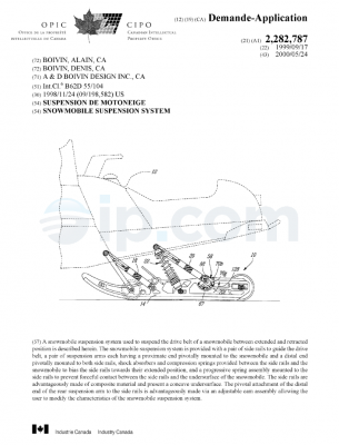
[0024] Fig. 9 is a side elevation view of an all-terrain vehicle provided with
track
assemblies according to a second embodiment of the present invention;
[0025] Fig. 10 is an inside perspective view of a mounting structure with a
longitudinal endless track belt mounted thereon according to the present
invention;
[0026] Fig. 11 a front elevation view of the mounting structure of FIG. 10
with the
longitudinal endless track belt mounted thereon according to the present
invention;
and
[0027] Fig. 12 an outside perspective view of the mounting structure of FIG.
10 with
the longitudinal endless track belt mounted thereon according to the present
invention.
[0028] It will be noted that throughout the appended drawings, like features
are
identified by like reference numerals.
DETAILED DESCRIPTION OF THE PREFERRED EMBODIMENT
[0029] A track assembly adapted to be retrofitted to a wheeled type all-
terrain
vehicle according to an embodiment of the present invention will now be
described in
details with reference to the appended drawings.
[0030] FIG. 1 shows an all-terrain vehicle 10 comprising a body 12 and four
track
assemblies 14 (only two are shown) arranged in a plane adjacent to each side
of the
vehicle 10. The four track assemblies 14 of the all-terrain vehicle 10 are
identical and
replace the conventional wheels of the all-terrain vehicle 10. Only one track
assembly 14, visible in FIG. 1, will be described hereinbelow.
[0031] Referring to FIGS. 2 and 10, it will be seen that the track assembly 14
comprises a longitudinal endless track belt 20 and a mounting structure to
mount the
endless track belt 20 to the vehicle 10. The mounting structure includes a
main
driving wheel 24, a pair of track driving wheels 26 disposed on opposite sides
of the
OR File No. 16902-5CA – 5 –
CA 02509440 2005-06-08
rotation axis of the main driving wheel 24 (only one is shown in FIG. 2), and
a
plurality of inner idler wheels 28 disposed by pair inside longitudinal
endless track
belt 20, and supports to interconnect the wheels 24, 26 and 28 as will be
described
hereinbelow. The idler wheels 28 define two laterally spaced-apart rows of
longitudinally spaced-apart wheels. As it can be seen from FIGS. 2, 7, 8, and
10-12,
main driving wheel 24 and track driving wheels 26 are external to endless
track belt
20.
[0032] Referring back to FIGS. 2 and 10, the endless track belt 20 is made of
an
elastomeric material and has an outer surface 30 for contact with the ground
and an
inner surface 32. Outer surface 30 is provided with transversal lugs 34 and is
adapted to engage with the driving wheels 26 of the vehicle 10. The endless
track
belt 20 is also provided with equidistant longitudinally spaced-apart openings
36 for
engagement with the track driving wheels 26. Adjacent openings 36 are
separated
by a bridging web 38. Bridging webs 38 are preferably covered with a
reinforcing
member 39 to increase the life expectancy of the endless track belt 20. The
endless
track belt 20 is wounded around the inner idler wheels 28 while the main
driving
wheel 24 and the track driving wheels 26 are located outside the loop defined
by
endless track belt 20.
[0033] Referring now simultaneously to FIGS. 2 to 4, 10, it will be seen that
track
driving wheels 26 are preferably provided in the form of cogwheels with
equidistant
teeth 40.
[0034] In the embodiment of FIG. 2, track driving wheels 26 are separated in
two
members. A first member 42 has teeth 40a that cooperates with the transversal
lugs
34 provided on the outer surface 30 of the endless track belt 20 while a
second
member 44 has teeth 40b that cooperates with bridging webs 38 between openings
36. Teeth 40a, 40b are spaced so that the distance between two consecutive
teeth
40a, 40b spans the distance separating consecutive transversal lugs 34 and
bridging
webs 38 respectively, in a meshing engagement, in such a way as to drive the
endless track belt 20. As it will be easily understood by one skilled in the
art, the
track driving wheel 26 can have only one member (FIGS. 3, 4, and 10-12) that
cooperates with either transversal lugs 34 of the endless track belt 20 or
bridging
OR File No. 16902-5CA – 6
CA 02509440 2005-06-08
webs 38, whichever the endless track belt 20 includes. In the embodiment of
FIG.
10, track driving wheels 26 cooperate with bridging webs 38 between openings
36.
Teeth 40 are spaced so that the distance between two consecutive teeth 40
spans
the distance separating consecutive transversal lugs 34 and/or bridging webs
38
respectively, in a meshing engagement, in such a way as to drive the endless
track
belt 20.
[0035] The main driving wheel 24 is retrofitted to the existing hub 50 of the
all-
terrain vehicle 10 (FIG. 2). Referring simultaneously to FIGS. 2-4, and 10, it
will be
seen that the main driving wheel 24 includes an inside plate 52 mounted to the
hub
50 and an outside plate 54 mounted to the inside plate 52 via a bolt and
spacer
assembly 56. Inside plate 52 has an outer surface 60 and an inner surface 62.
A
plurality of uniformly circumferentially distributed engaging members 64 are
provided
on either the outer surface 60 (FIG. 2) or the inner surface 62 (FIGS. 3-5) of
inside
plate 52. Engaging members 64 cooperate with the teeth 40 of track driving
wheels
26. Equidistant engaging members 64 are spaced so that the distance between
two
consecutive engaging members 64 spans the distance separating consecutive
teeth
40, in a meshing engagement, in such a way as to drive track driving wheels
26. As
it will be easily understood by one skilled in the art, engaging members 64
can also
be the spacers between the inside and outside plates 52, 54 (FIGS. 10-12) or
be
mounted on either the inner or outer surface of outside plate 54. According to
one
embodiment of the present invention, the engaging members 64 are provided in
the
form of rollers to provide a smooth torque transmission from the main driving
wheel
24 to the track driving wheel 26.
[0036] Wheels 24, 26 and 28 are interconnected with an inside mounting plate
70
and an outside mounting plate 72, wheels 24 and 26 being disposed externally
to
track belt 20. Inside plate 52 of main driving wheel 24 is connected to
outside
mounting plate 70 with a spacer 80. Referring to FIG. 6, it will be seen that
spacer 80
has three portions 80a, 80b, and 80c, each portion having a different
diameter.
Inside plate 52 is rotatably mounted on spacer 80. Referring back to FIGS. 2-
4, 10
and 12, it will be seen that each track driving wheels 26 is rotatably mounted
on a
spacer 82 which connects inside and outside mounting plates 70, 72. Similarly,
each
pair of inner idler wheels 28 is rotatably mounted on a spacer 84 which
connects
OR File No. 16902-5CA – 7 –
CA 02509440 2005-06-08
inside and outside mounting plates 70, 72. Spacers 80, 82, and 84 are fastened
to
inside and outside mounting plates 70, 72 with fasteners 86 inserted in
apertures in
inside and outside mounting plates 70, 72 but they could be welded thereon
without
departing from the scope of the invention. A reinforcing plate 90 (FIGS. 2-5)
can
interconnect spacer 80 and spacers 82. Reinforcing plate 90 reinforces outside
plate
mounting 72 and stiffens the track assembly 14.
[0037] Each of the inner idler wheels 28 has a peripheral portion in contact
with
the inner surface 32 of the track belt 20. In a preferred embodiment, track
assembly
14 has a plurality of pairs of inner idler wheels 28. Each pair is rotatably
mounted on
each spacer 84. Moreover, any number of inner idler wheels 28 can be rotatably
mounted on each spacer 84 without departing from the scope of the invention.
[0038] As it will be easily understood by one skilled in the art upon
inspection of
FIGS. 2, 3, 10, and 12, the shape of the endless track belt 20 can be modified
by
adjusting the vertical position of the front and rear idler wheels 28a, 28b.
As it can be
seen, both ends of inside and outside mounting plates 70, 72 have several
round
apertures 91, at various height, in which spacer 84 can be fastened. By
mounting
spacer 84 in a higher round aperture 91 positioned at one end, endless track
belt 20
has a C-shape at that end as seen in FIGS. 2 and 10. On the opposite, by
mounting
spacer 84 in a lower round aperture 91 at another end, endless track belt 20
has a
substantially flat shape at that end. An endless track belt 20 having a C-
shape is
more maneuverable while an endless track belt 20 that is substantially flat
gives
better performance since it has a wider supporting footprint.
[0039] It is also possible to adjust the tension of endless track belt 20 with
a
tension adjusting assembly. As it can be seen from FIGS. 2, 3, 10, and 12, one
end
of inside and outside mounting plates 70, 72 includes several slotted
apertures 92,
one slotted aperture 92 for each round aperture 91. Slotted aperture 92
receives a
fastener 94 used to rotatably mount the wheels 28 to the assembly. By sliding
the
fastener 94 in the slotted aperture 92, it is possible to increase or decrease
the
tension on the track belt 20. To adjust and maintain the track tension, a cam
element
96, having an outer periphery provided with notches 98 located at different
distances
from the attachment point of the cam element 96, is mounted to the fastener
94. By
OR File No. 16902-5CA – 8 –
CA 02509440 2005-06-08
selecting which notch 98 is in contact with a fixed pin (not shown) of the cam
element 96, a predetermined tension may be maintained. It is to be noted that
the
cam element 96 can be provided with a handle (not shown) to facilitate the
manipulation by a user. It is also understood that the tension adjusting
assembly can
be located at the opposite end of the inside and outside mounting plates 70,
72.
[0040] Inside mounting plate 70 has a central aperture 100 (FIG. 5) for
inserting
conventional hub 50 of the all-terrain vehicle 10 therein. It also has small
apertures
102 all around the central aperture 100 for inserting fasteners (not shown)
therein for
fastening the track assembly 14 to the vehicle 10.
[0041] It is possible to adjust the height of the track assembly 14 by
modifying
the position of driving track wheels 26 relatively to main driving wheel 24.
As it can
be seen from FIG. 4, inside and outside mounting plates 70, 72 are provided
with a
plurality of round apertures 104 in which spacer 82 can be fastened with
fasteners
86. A round aperture 104 on inside mounting plate 70 faces a corresponding
round
aperture 104 on outside mounting plate 72. By fastening spacer 82, on which
driving
track wheel 26 is rotatably mounted, in different round apertures 104, the
height of
track assembly 14 is modified. Inside and outside mounting plates 70, 72 are
also
provided with a central round aperture 104. If track assembly 14 only has one
track
driving wheel 26 operatively engaged with the main driving wheel 24 and the
longitudinal track driving belt 20, spacer 82, on which the single driving
track wheel
26 is rotatably mounted, is preferably fastened with fasteners 86 in central
round
aperture 106 (FIG. 2). However, with two driving track wheels 26, the vehicle
rolling
is smoother.
[0042] The track assembly 14 also allows to replace any of the driving wheels
24,
26 with another wheel having a different diameter. Changing the driving wheels
24,
26 allows to modify the gear ratio of the vehicle 10.
[0043] It is also possible to cover the external gearing of the track assembly
14,
which includes main driving wheel 24 and driving track wheels 26, with a
protective
cover (not shown). The protective cover prevents the insertion of undesired
objects,
such as branches, in the track assembly 14 and further acts to reduce the
security
OR File No. 16902-5CA – 9 –
CA 02509440 2005-06-08
risk associated with operating such a track assembly 14, for the vehicle’s
user or any
other person in proximity of the track assembly 14.
[0044] As stated hereinabove, the track assembly 14 is provided with an
external
gearing, i.e. the main driving wheel 24 and the track driving wheel are
located
externally of endless track belt 20. The endless track belt 20 has a plurality
of
equidistant openings 36 separated by bridging webs 38, which ensure a positive
engagement with the teeth 40 provided on the outer circumference of track
driving
wheels 26. Moreover, the main driving wheel 24 is provided with a plurality of
equidistant engaging members 64, which ensure a positive engagement of the
teeth
40. In operation, the main driving wheel 24 is coupled to a drive shaft, via
the hub 50,
connected to an engine (FIGS. 2, 7, and 8), in such a way that the engine
drives the
main driving wheel.24 in rotation. The main driving wheel 24 thus drives both
track
driving wheels 26 in rotation by meshing engagement of the teeth 40 and the
equidistant engaging members 64. The track driving wheels 26 drives the
endless
track belt 20 in rotation by the meshing engagement of the teeth 40 with the
equidistant openings 36 separated by bridging webs 38 of the endless track
belt 20.
It is further to be understood that the transversal lugs 34 on the external
circumference surface of the endless track belt 20 respectively exert a
positive
mechanical connection with the underlying ground surface that contributes to
propel
the vehicle 10.
[0045] In another embodiment, the track assembly 14 includes a steering
mechanism that facilitates the steering of the all-terrain vehicle 10.
Referring to
FIGS. 3 to 6, it will be seen that the steering mechanism includes two
secondary
braking systems. Each braking system is operatively associated with a track
assembly 14 disposed at the front of the all-terrain vehicle 10, mainly with
the main
driving wheel 24 of the assembly 14. Each secondary braking system includes a
brake 140. The brake 140 is disposed proximate to the main driving wheel 24.
In
FIGS. 3 to 6, the brake 140 is mounted proximate to the outside plate 54 and
abuts
against the latter when the braking system associated with the brake 140 is
activated. The brake 140 abutting the outside plate 54 slows down the rotation
movement of the main driving wheel 24 and consequently the rotation movement
of
the track belt 20. When the all-terrain vehicle 10 negotiate a turn in a
predetermined
OR File No. 16902-5CA – 10 –
CA 02509440 2005-06-08
direction, the braking system associated with the main driving wheel 24
located
inside the desired turn can be activated to provide better maneuvering of the
vehicle.
The main driving wheels 24 of the front track assemblies 14 have therefore a
different rotation speed and the vehicle 10 turns in the direction of the main
driving
wheel 24 having the slowest rotation speed. Moreover, for tracked vehicle,
since the
rotation pivot is offset relatively to the track belt 20, the vehicle steering
is even more
facilitated.
[0046] The steering mechanism can be activated manually with a handle, a
pedal, or the like or automatically while turning the steering of the vehicle.
The
steering mechanism can be combined with the main braking system of the vehicle
without departing from the scope of the invention. Each braking system can be
operatively associated simultaneously with a front and a rear driving wheels
on the
same side of the vehicle 10. Brakes 140 can be operatively associated with the
track
driving wheels 26, on the inside plate 52 of the main driving wheel 24 or both
inside
and outside plates 52, 54 without departing from the scope of the invention.
Preferably, the plates) or wheels) associated with each brake 140 is made in
steel
or any other appropriate material.
[0047] Of course, one skilled in the art could design another arrangement of
the
mounting assembly of the endless track belts 20 to the vehicle 10 to obtain
this
external driving wheel feature without departing from the spirit and nature of
the
present invention.
[0048] Alternatively, the track assembly 14 could only be comprised of a main
driving wheel 24 directly engaged with the longitudinal track driving belt 20.
In that
case, the main driving wheel 24 would be provided with equidistant teeth 40 on
its
periphery for meshing engagement with either the transversal lugs 34 and/or
the
equidistant openings 36 separated by bridging webs 38. Furthermore, the motor
of
the all-terrain vehicle 10 preferably turns in the opposite direction.
[0049] As people in the art will understand, the all-terrain vehicle of the
present
invention, provided with four endless track assemblies, can be used for a wide
range
of operations and terrain, while being highly mobile and offering good running
performance. The endless track structure maintains an adequate configuration
over
OR File No. 16902-5CA – 11 –
CA 02509440 2005-06-08
a variety of surfaces. Since it does not have sliding shoes, it can be used on
any
ground surface.
[0050] Moreover, the track assembly 14 can be used with all-terrain vehicle 10
of
any cylinder capacity. As it can be seen in FIGS. 1 and 9, the track assembly
14
provides support longitudinally under almost the entire all-terrain vehicle
10,
including under the lower portion 120 of the vehicle 10. It provides a wide
supporting
footprint that performs adequately in deep snow conditions. The snow projected
on
the driver while using an all-terrain vehicle 10 having the track assembly 14
is
negligible. Moreover, as it can be seen in FIGS. 1 and 9, the wings of the all-
terrain
vehicle 10 are clear from the track assemblies 14. Therefore, even if the
track
assembly 14 pivots around hub 50, the risk of interference with the wings is
negligible.
[0051] Referring back to FIGS. 1, 7, 8, and 10-12, it will be seen that either
the
vehicle 10 or the track assembly 14 can have a rotation stopper 130 that stops
the
rotation movement of track assembly 14 around hub 50. In one embodiment,
rotation
stopper 130 is mounted on spacers 84 with fasteners 132 and proximate to
inside
mounting plate 70. Rotation stopper 130 has a slot 134 in the middle therein.
Vehicle
is provided with a member 136 (FIGS. 10-12) having a portion slidably inserted
in
slot 134 and another portion mounted on the vehicle 10. The rotation movement
of
track assembly 14 stops when the member 136 abuts one end of slot 134.
Rotation
stopper 130 prevents the track assembly 14 to enter in contact with a vehicle
wing
and spoil the latter.
[0052] It will be obvious to people skilled in the art that the present
invention can
be applied both in the case of a two-wheel drive vehicle wherein the power is
typically applied only to the rear track belt assemblies and the front track
assemblies
merely facilitate steering, and in the case of a four-wheel vehicle, wherein
power is
independently provided to each one of the four track assemblies. It is also
understood that, although the present invention has been described in the
context of
a four-wheeled all-terrain vehicle (ATV), it could also be applied to other
vehicles
including various straddle-type vehicles, such as dirt bikes, motorcycles and
three-
wheeled ATV.
OR File No. 16902-5CA – 12 –
CA 02509440 2005-06-08
[0053] As will be further understood by one skilled in the art, the all-
terrain
vehicle 10, equipped with track assemblies according to the present invention,
may
be viewed as a snow vehicle since it may be used on snow as efficiently as
conventional snow vehicles such as snowmobiles, for example. The wide
supporting
footprint of the track assemblies is an important factor allowing this good
performance. However, the absence of sliding shoes allows the use of the all-
terrain
vehicle on harder surface without the usual drawbacks of tracked vehicles.
[0054] Interestingly, the present track assembly system can equip all four
wheels
of an all-terrain vehicle or only the front or rear wheels thereof. A further
possibility
would be to use track assemblies according to the present invention in place
of the
rear wheels of a vehicle, while mounting skis in place of the front wheels
thereof.
Another important advantage of the track assembly 14 is that the same track
assembly 14 can be mounted in any position on the vehicle (front, rear, left
and
right).
[0055] The embodiments of the invention described above are intended to be
exemplary only. The scope of the invention is therefore intended to be limited
solely
by the scope of the appended claims.
OR File No. 16902-5CA – 13 –

 Français