Adjustable apparatus and kit for a coupled snowmobile suspension (CA)

Adjustable apparatus and kit for a coupled snowmobile suspension – CA 2358154 A1 – IP.com

Canadian Application Publication


Title (French)

Appareil reglable et trousse pour la suspension couplee d’Une motoneige

Abstract (English)

The present invention provides a apparatus as an after-market, upgrade kit constructed and arranged to be installed onto an coupled snowmobile suspension system that, when installed, provides for quick and easily accessible coupling adjustment. Specifically, the upgrade kit of the present invention is configured to be installed onto the Polaris® line of snowmobiles. The upgrade kit includes a shaft having an axis of rotation, a pair of coupling blocks, and an indexer plate. The coupling blocks are adapted to be fixedly connected relative to the axis of rotation at each end of the shaft so that a torque in the shaft will be transmitted to the coupling blocks. The coupling blocks have a plurality of sides corresponding to a plurality of positions of the coupling blocks, each of the sides being located at a different distance from the axis of the shaft when the coupling blocks are connected to the shaft. The indexer plate is adapted to engage one of the coupling blocks at a selected positions of the coupling blocks. The shaft is constructed and arranged to be mounted between a longitudinal pair of slide rails of the snowmobile suspension with two bolts, and the coupling blocks are adapted to be rotated about the axis to thereby adjust the coupling of the snowmobile. A pair of support brackets are attached on the outside of the slide rails to the shaft to pass forces seen by the coupling blocks to the slide rails. Adjustment of the coupling blocks is accomplished by applying a torque to one of the bolts in a direction which tightens the bolt.

Inventors

BOIVIN, ALAIN [+1] [-1]
ST-HENRI DE LÉVIS, Q1, CA

BOIVIN, DENIS
LEVIS, Q1, CA

Applicants

BOMBARDIER INC.
VALCOURT, Q1, CA

Assignees

BOMBARDIER INC. [+3] [-3]
VALCOURT, Q1, CA

BOIVIN, ALAIN
ST-HENRI DE LÉVIS, Q1, CA

BOIVIN, DENIS
LEVIS, Q1, CA

BOMBARDIER RECREATIONAL PRODUCTS INC.
VALCOURT, Q1, CA

Priority

US 237,489 P  04-Oct-2000

Classifications

International (2006.01): B62M 27/02; B62B 17/04; B62D 55/07; B62D 55/104
International: B62D 55/104; B62D 55/07
Cooperative (2013.01.01): B62B 17/04; B62M 2027/026; B62M 27/02
European: B62M 27/02; B62B 17/04

Language of Filing

English

Attorney, Agent or Firm

Osler, Hoskin & Harcourt LLP
CA

Also Published As

US 2002/0060102 A1

application

Adjustable apparatus and kit for a coupled snowmobile suspension

May-2002


US 6478098 B2

patent

Adjustable apparatus and kit for a coupled snowmobile suspension

Nov-2002

Adjustable apparatus and kit for a coupled snowmobile suspension – CA 2358154 A1 – IP.com

CA 02358154 2001-10-03
ADJUSTABLE APPARATUS AND KIT FOR A COUPLED
SNOWMOBILE SUSPENSION
Field of the Invention
This invention relates to snowmobile suspension systems, and more particularly
to coupled
suspension systems, and even more particularly to an apparatus, in the form of
an after-market
upgrade kit, that permits, when installed, quick and easily accessible
coupling adjustment.
Background of the Invention
Tracked vehicles such as snowmobiles have rear suspension systems generally
consisting of
front and rear suspension arms pivotally mounted on shafts, which are
rotatably connected to the
frame of the snowmobile, and a slide frame, which comprises a pair of
laterally spaced apart slide
rails or longitudinal skids interconnected transversely on opposing lateral
sides of the machine. The
slide rails are in sliding contact with an endless belt which provides ice and
snow surface contact
and a friction drive for the snowmobile. In many current arrangements, front
and rear suspension
arms pivotally interconnect the chassis to the slide frame.
It is generally known in the art that independent movement of the front and
rear suspension
arms is less desirable than a suspension system in which the front and rear
suspension arms are
coupled. In an uncoupled suspension system, when the front suspension arm
deflects as it contacts a
bump, the independent rear suspension arm remains in its ride or fully
extended position. This
results in an angle of incidence between the slide rails and the bump. Unless
the impact is so large
that it compresses the rear suspension arm spring and shock absorber assembly,
thereby flattening
1

CA 02358154 2001-10-03
the angle of incidence, the slide rails will act as a ramp forcing the rear of
the snowmobile upward.
That is, with the slide rails angled in an upward incline due to the
independent deflection of the
front suspension arm, but not the rear suspension arm, the snowmobile will hop
over the bump,
imparting a secondary jolt which increases in intensity with the speed of the
snowmobile. This
secondary jolt also results in a loss of control and a reduction of the speed
of the snowmobile.
On the other hand, a coupled suspension system is one in which, for example,
the rear
portion of the suspension system reacts (i.e., is coupled) to the compression
experienced by the front
portion of the suspension system as the snowmobile passes over a bump in the
terrain. In effect, the
bump is “communicated” to the rear portion of the suspension, causing the rear
portion to be pulled
upward toward the chassis before the rear portion actually reaches the bump.
This reduces the angle
of incidence between the slide rail and the bump, which thereby reduces the
secondary jolt
experienced by the rider. As a result, a coupled suspension system provides
for an improved ride
because the coupled suspension is better suited to adjust to varying terrain
conditions.
Manufacturers have developed a variety of ways to provide coupled suspension
systems,
which typically involve restricting the amount of longitudinal movement of the
rear suspension arm.
Such systems are shown in U.S. Patents Nos. 5,881,834, 5,692,579, 5,667,031,
and 5,944,134.
The suspension system disclosed in Polaris’ 5,692,579 (“‘579”) patent is shown
in Figs. 1-4,
where Fig. 1 shows the overall suspension system removed from the snowmobile,
and Figs. 2-4
show the design approach used to couple the suspension system. As disclosed in
the ‘579 patent and
depicted in Figs. 2 and 4, the linkage of the rear suspension arm 20 with the
lower pivot arm 26
permits the front of the slide rails 10 to rise substantially independently of
the rear portion of slide
rails. During this independent movement of the front portion of the
suspension, the lower pivot arm
26 pivots from the rearward position shown in solid lines in FIG. 2 to the
forward position depicted

2

CA 02358154 2001-10-03
in broken lines. At the point which the front surface 27 of the lower pivot
arm 26 engages the front
adjuster block 30, further independent upward movement of the front end of the
suspension is
prevented. That is; further upward movement of the front of the slide rails 10
is mechanically linked
through the adjuster block 30 to the rear suspension arm 20, causing upward
movement of the rear
of the suspension (the rate of upward movement of the rear of the suspension
may or may not be
equal to the rate of movement of the front of the suspension, depending on the
specific geometric
configuration of the system).
The degree of independent movement afforded to the front of the suspension
rails 10 is
dependent on the distance between the rear stop 32 and the front adjuster
block 30 in comparison to
the width of the lower pivot arm 26. The rear surface 31 of the front adjuster
block 30 thus provides
a limit on the relative forward movement of the lower end of the suspension
arm 20 with respect to
the slide rail 10.
The Polaris~ system of the ‘579 patent further provides variability to the
position of this
limit, thereby giving the rider some control over the performance
characteristics of the suspension.
This variability is provided by using rectangular adjuster block 30, which has
four surfaces that are
each positioned at varying distances from the block’s central mounting point,
as indicated by
distances “dl” through “d4” in Fig. 4. By rotating the block to select one of
the surfaces, the
position of the limit with respect to the lower end of the suspension arm 20
can be controlled.
However, with the above Polaris~ system, it is difficult for the rider to make
a desired
adjustment to the adjuster block 30, especially when the rider is in the
field. To make an
adjustment, the rider must first loosen the central mounting point (a bolt).
Then, the rider must
manage to rotate adjuster block 30, either with his fingers or with the aid of
another tool, to the

3

CA 02358154 2001-10-03
desired location, and then retighten the central mounting point. The rider
must then repeat these
steps for the adjuster block on the opposite side of the slide rail.
Considering that the rider may
wish to make such adjustments while in the field, where he/she would encounter
other obstacles,
such as deep snow, cold weather, and generally unfavorable conditions for
handling tools and
equipment, it is apparent that making such adjustments to the adjustable block
30 in order to
compensate for differing terrain conditions is difficult with the above
Polaris~ system.
It is therefore the object of this invention to provide an apparatus, in the
form of an after-
market upgrade kit, for installation onto a coupled snowmobile suspension
system of the kind
described in Patent No. 5,692,579 that, when installed, allows for a quick and
easy adjustment of the
front to rear coupling.
It is further an object of the present invention to provide an apparatus, in
the form of an
after-market upgrade kit, specifically configured to be installed onto the
Polaris~ line of
snowmobiles.
Summary of the Invention
It is the object of the present invention, therefore, to provide an apparatus
and an after-
market upgrade kit constructed and arranged to be installed onto a coupled
snowmobile suspension.
The upgrade kit includes a shaft having an axis of rotation, a pair of
coupling blocks, and an indexer
plate. The coupling blocks are adapted to be fixedly connected relative to the
axis of rotation at
each end of the shaft so that a torque in the shaft will be transmitted to the
coupling blocks. The
coupling blocks have a plurality of sides corresponding to a plurality of
positions of the coupling

4

CA 02358154 2001-10-03
blocks, each of the sides being located at a different distance from the axis
of the shaft when the
coupling blocks are connected to the shaft. The indexer plate is adapted to
engage one of the
coupling blocks at a selected positions of the coupling blocks. The shaft is
constructed and
arranged to be mounted between a longitudinal pair of slide rails of the
snowmobile suspension, and
the coupling blocks are adapted to be rotated about the axis to thereby adjust
the coupling of the
snowmobile.
Other obj ects and advantages of the present invention will be realized in
accordance with the
following detailed description, appended drawings, and claims.
Brief Description of the Drawings
The various embodiments of the present invention are shown throughout the
drawings, in
which:
Fig. 1 is a perspective view of a coupled snowmobile suspension of the prior
art;
Fig. 2 is a plan view of Fig. 1, and also shows the coupling apparatus;
Fig. 3 is an enlarged view of the coupling apparatus of Fig. 2;
Fig. 4 is an enlarged view of the coupling block of Figs. 2 and 3 of the prior
art;
Fig. 5 is a perspective view of the preferred embodiment of the apparatus of
the present
invention showing the assembly thereof before attachment to the snowmobile
suspension;
Fig. 6 is a plan view of the shaft of the upgrade kit of the preferred
embodiment;
Fig. 6B is a section view of the rectangular portions of the main shaft of
Fig. 6;
Fig. 6C is a plan view of a second embodiment of the main shaft, where the
coupling blocks
are integrally formed with the main shaft;
Fig. 7 is a plan view of a coupler block of the upgrade kit of the preferred
embodiment;

CA 02358154 2001-10-03
Fig. 8 is a side view of a coupler block of the upgrade kit of the preferred
embodiment;
Fig. 9 is the plan view of Fig. 7 showing dimensional attributes;
Fig. 10 is a perspective view of a coupling block having mounted thereto a
ball spring
plunger, which is the preferred embodiment of a protrusion of the upgrade kit;
Fig. 11 is a side view of Fig. 10;
Fig. 12 is a side view of a coupling block having mounted thereto a second
embodiment of a
protrusion mounted to a coupling block;
Fig. 13 is a side view of a coupling block having mounted thereto a third
embodiment of a
protrusion mounted to a coupling block;
Fig. 13B is a perspective view of a second embodiment of the indexer plate and
coupling
blocks, where the indexer plate has mounted thereto the protrusions of Figs.
11, 12, 13, and the
coupling block includes a plurality of depressions;
Fig. 14 is a plan view of the indexer plate of the upgrade kit of the
preferred embodiment;
Fig. 15 is a plan view of a support plate of the upgrade kit of the preferred
embodiment;
Fig. 16 is a plan view of a Polaris~ XTR.A-10 snowmobile suspension system
without the
upgrade kit installed;
Fig. 17 is an enlarged view of the coupling portion of Fig. 16;
Fig. 18 is a plan view of a portion of the suspension system of Fig. 16 with
the upgrade kit
installed;
Fig. 19 is a top view of the upgrade kit installed onto the Polaris~ XTRA -10
snowmobile
suspension system of Fig. 16; and
Fig. 20 is a depiction of the position of the lower arm engaged with a coupler
block in two
different positions of the coupler block.
6

CA 02358154 2001-10-03
Fig. 21 is a snowmobile comprising the upgrade kit of the present invention.
Detailed Description
Referring now more particularly to the Figures, wherein like reference numbers
are used for
like components where applicable, the apparatus of the present invention,
which is also referred to
as an upgrade kit, is generally indicated at 40 and is illustrated in Fig. 5.
Generally, the upgrade kit
40 is constructed and arranged to be installed onto an adjustably coupled,
snowmobile suspension
system, so that when installed, the adjustment of the coupling is made quicker
and easier. More
specifically, the upgrade kit 40 is configured to be assembled onto the
Polaris~ line of snowmobiles
that are originally manufactured with an adjustable, coupled suspension
systems, as described above
with reference to Figs. 1-4.
Refernng to the Fig. 5, the upgrade kit 40 comprises, among other components,
a shaft 42,
two adjustable coupling blocks 46, 48, an indexer plate 50, two bolts 54, 58,
and two plate brackets
62 & 66. Figure 5 shows the upgrade kit 40 as an assembly, but not installed
onto the suspension
system, and Figs. 6-1 S show each component separately. The adjustable
coupling blocks 46, 48 are
hereinafter referred to as the coupling blocks 46, 48, and shaft 42 is also
referred to as the main
shaft 42.
As seen in Figs. 5 and 6, the main shaft 42 comprises a cylindrical portion 68
and two
rectangular portions 70, 72 mounted at each end of the main shaft 42. The axis
of the main shaft 42
is designated as reference numeral 74. The corners of the rectangular portions
70, 72 preferably
include longitudinal chamfers 76 that extend a length L3 from the end of the
main shaft 42, which
are configured to accommodate the coupling blocks 46, 48, described below.
Each end of the main
7

CA 02358154 2001-10-03
shaft 42 has a threaded bore 78 formed to a depth of length L3 therein. The
threaded bores 78
accommodate bolts 54 and 58 in order to mount the upgrade kit 40 to the
snowmobile suspension.
The rectangular portions 70, 72 and cylindrical portion 68 of the main shaft
are preferably
integrally formed with the cylindrical portion 68 of the main shaft 42, and is
preferably machined
from a single piece of machine stock. Of course, the main shaft 42 may be
formed from other
manufacturing techniques, such as by a casting, or the rectangular portions
70, 72 can be separately
formed and welded or otherwise connected to the cylindrical portion 68 to form
main shaft 42.
Also, the entire main shaft 42 may be rectangular, and the cylindrical portion
68 need not be
present. In the preferred embodiment, the main shaft 42 is made of aluminum.
However, it is
contemplated that any other suitable material can be used, as long as the
material selected is
sufficiently strong and rigid.
Each coupling block 46, 48, shown separately in Fig. 7, is a generally
rectangularly-shaped,
rigid structure and includes a generally rectangular bore 80. The dimensions
of the rectangular bore
80 are substantially the same as the dimensions of the rectangular portions
70, 72 of the main shaft
42, such that the rectangular portions 70, 72 therein can be matingly
inserted. The rectangular
portions 70, 72, therefore, transmit torque from the main shaft 42 to the two
adjuster coupling
blocks 46, 48 during rotation of the main shaft. The axis 74 of main shaft 42,
when inserted into
coupling blocks 46, 48, is coincident with the centers of the rectangular
bores 80. The corners of
the rectangular bore 80 are, preferably, fillet radiused in a size to prevent
interference with the
chamfers 76 of the rectangular portions 70, 72. Also, the outside corners of
each coupling block 46,
48 are preferably rounded with radii Rl, R2, R3, and R4 to facilitate rotation
of the blocks.
Although in the preferred embodiment the adjuster coupling blocks 46, 48 are
separate
structures from the main shaft 42, it is also contemplated that the adjuster
coupling blocks 46, 48
8

Adjustable apparatus and kit for a coupled snowmobile suspension – CA 2358154 A1 – IP.com

CA 02358154 2001-10-03
may be integrally formed with the main shaft 42 (see Fig. 6C). That is, the
main shaft 42 would
comprise coupler blocks 46, 48 integrally formed at each end of the main
shaft. In such case, the
rectangular portions 70, 72 for transmitting torque to the coupling blocks
would not be required.
Whether integrally formed or as a separate structure, each coupler block 46,
48 in the
preferred embodiment includes a plurality of sides corresponding to a
plurality of positions of the
coupling blocks. In the preferred embodiment, the coupling blocks 46, 48
include four sides 84, 85,
86, 87 that are each located at a different distance from the axis 74 when the
coupling blocks are
connected to the main shaft 42. As shown in Fig. 9 for clarity, each side 84,
85, 86, and 87 is
located a distance “d5”, “d6”, “d7”, and “d8”, respectively, from the center
rectangular bore 80 (or,
equivalently, the axis 74 of the main shaft 42). Adjustment of the coupling
system after the upgrade
kit 40 is installed onto the snowmobile suspension system is accomplished by
rotating the coupling
blocks 46, 48 so that the desired side is selected for use (i.e., to engage
surface 27 of lower pivot
arm 26, shown in Fig. 3), which is discussed in detail below.
In the preferred embodiment where the coupling blocks are separate structures
from the
main shaft, the adjuster blocks 46, 48 are made of ultra high molecular weight
(UHMW) plastic,
which is chosen for its light weight but high strength, rigidity, and superior
wear characteristics.
However, it will be understood to those skilled in the art that other suitable
materials could also be
used, such as steel alloy. If the coupling blocks are integrally formed with
the main shaft 42, then,
of course, the coupling block material would be the same as the main shaft
material.
In the preferred embodiment, at least one of the coupling blocks 46, 48
includes a cylindrical
bore 82 formed therethrough, and a ball spring plunger 90 is inserted therein,
as shown in Figs. 10
and 11. The ball spring plunger 90 acts as an index stopping “pointer” or
protrusion for indexing the
coupling blocks 46, 48 at a selected position in conjunction with indexer
plate 50, which will be
9

CA 02358154 2001-10-03
described below. The ball spring plunger 90 is of the conventional type, and
generally includes a
protrusion or ball 96 resiliently disposed, by a spring 97, against an
interior edge of flange stop 94.
The spring 97 is disposed within a cylindrical chamber defined by cylindrical
walls 92, the diameter
of which is slightly larger than the rectangular bore 80 so that the ball
spring plunger 90
interferingly fits within bore 80.
Although a ball spring plunger 90 is used in the preferred embodiment, it will
be understood
by those skilled in the art that other mechanisms can also be used to perform
indexing of coupling
blocks 46, 48, such as, for example, a resilient cantilever spring 98 formed
with a protrusion or ball
99, shown in Fig. 12, or a bevel spring 100 formed with a protrusion or ball
101, as shown in Fig.
13.
Indexer plate 50, shown separately in Fig. 14, has a through-hole 106 formed
therethrough at
one end and a through-hole 108 formed therethrough at its other end, which is
also located
approximately centrally of a generally circular portion 110 of indexer plate
50. Four equally
spaced-apart through bores 112, 114, 116, 118 are formed toward the periphery
of circular portion
110 in surrounding location of through-hole 108, and all the holes are located
at the same radial
distance from the center of through-hole 108. When the upgrade kit is
installed onto the
snowmobile, through-hole 108 receives bolt 54 for positioning the indexer
plate 50 relative to the
coupling blocks (bolt 54, along with bolt 58, also pivotally mounts the main
shaft 42 to the slide
rai1s10), and one of the holes (i.e., either bore 112, 114, 116, or 118) is
aligned and engaged with the
ball spring plunger 90 to establish a position of the coupling blocks 46, 48.
Through-holes 112,
114, 116, and 118 may also be depressions in the indexer plate of sufficient
size to sufficiently
engage the protrusion or ball 96 of the ball spring plunger 90. The other end
of indexer plate 50 is
bolted via through-hole 106 to the slide rail 10 of the snowmobile to thereby
fixedly define the

CA 02358154 2001-10-03
position of the four holes 112, 114, 116, 118 with respect to the coupling
blocks 46, 48. The
distance between the center of holes 106 and 108 is designated as L11. The
indexer plate 50 is
preferably made of brass plate having a thickness of 0.074 inches. However,
any other suitable
material and appropriate thickness could also be used.
Although in the preferred embodiment a protrusion is mounted to one of the
coupling blocks
for engagement with a depression (or hole) of the indexer plate, it is
contemplated that the indexer
plate 50, rather than the coupling blocks 46, 48, may mount the protrusions.
That is, as shown in
Fig. 13B, the ball spring plunger 90 may be mounted to indexer plate 50 for
engagement with a
plurality of depressions or bores 109 formed in one of the coupling blocks
(see Fig. 13B).
Each plate bracket 62, 66, shown separately in Fig. 15, defines two through-
holes 122, 124
formed therethrough at each end therein. The size and proximity of the through-
holes 122, 124
correspond with the through-holes 106, 108 of indexer plate 50. Thus, the
distance, L12, between
through-holes 122 and 124 is substantially the same as the distance L11.
Through-hole 124 of plate
bracket 62 receives bolt 54, which also is received by through-hole 108 of
indexer plate 50, and
through-hole 124 of plate bracket 66 receives bolt 58, as shown in the
assembly drawing of Fig. 5.
Through-hole 122 and through-hole 106 receives another bolt 130 (see Fig. 19),
thus fixedly
mounting both the plate bracket 62 and the indexer plate to the slide rail 10
(discussed below). Plate
bracket 66 of the opposite side of the snowmobile is likewise fixed to the
slide rail, but without an
indexer plate. The plate brackets 62, 66 provide support between the coupling
blocks 46, 48 and the
slide rail 10. That is, the brackets 62, 66 pass forces seen by the coupler
system (when, for example,
the lower arm 62 is urged against coupling blocks 46, 48) to the slide rails,
which are made of
aluminum. Because they are designed to carry stress, the plate brackets 62, 66
are preferably made
of 3/16″ brass plate. However, it will be understood to those skilled in the
art that the thickness or
11

CA 02358154 2001-10-03
material used is not intended to be limiting, and that other materials and/or
thicknesses can be used
as long as the combination selected is sufficiently strong and rigid.
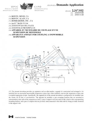
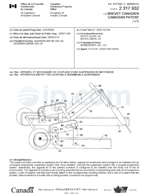
Refernng now to Figs. 16-20, the components of the upgrade kit 40 described
above are
constructed and arranged to be assembled and attached to the slide rails 10 of
a coupled snowmobile
suspension system. More specifically, upgrade kit 40 is configured to be
assembled onto a Polaris~
snowmobile suspension system of the type which is generally depicted, without
the upgrade kit 40
attached, in Figs. 1-4. Even more specifically, the upgrade kit 40 is
configured to be assembled
onto the Polaris~ XTRA-10 snowmobile suspension system, which is depicted in
Figs. 16 and 17.
As seen in Figs. 16 and 17 of the XTRA-10 model, the coupler block 30, rear
stop 32, lower pivot
arm 26, are slightly modified from the Polaris~ model shown in Figs. 1-4. The
differences,
however, are not substantial, so the same reference numerals are used for
equivalent elements.
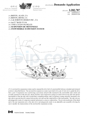
Generally, the suspension system of the Polaris~ snowmobile includes a slide
frame 13,
which comprises a pair of laterally spaced apart slide rails 10 or
longitudinal skids interconnected
transversely on opposing lateral sides of the machine. The slide frame 13 is
interconnected to the
snowmobile chassis 14 by a front and rear suspension arm, 12 and 20,
respectively. As more clearly
seen in Fig. 17, each coupling block 30 is mounted to the slide rails 10 with
bolts 126, and each rear
stop 32 is mounted to the slide rails 10 with bolts 128. As discussed above
and described in the
‘579 patent, the lower pivot arm 26 can rotate within the limits defined by
rear surface 31 of the
front adjuster block 30 and rear stop 32. The remainder of the suspension
system is known in the art
and described in the ‘579 patent, and therefore need not be described in
detail.
Referring now to Figs. 18 and 19, the attachment of upgrade kit 40 to the
Polaris~
suspension system will now be described. First, after raising and supporting
the suspension off the
ground, the bolts 126 and 128, which mount adjuster blocks 30 and rear stop
32, are removed. The
12

CA 02358154 2001-10-03
adjuster blocks 30 are then removed from the slide rails 10. Then, after
mounting the coupling
blocks 46, 48 of the upgrade kit 40 to the rectangular portions 70, 72 of main
shaft 42, the assembly
is installed so that coupling blocks 46, 48 replace the original blocks 30.
The main shaft assembly
(i.e., main shaft 42 and blocks 46, 48) is disposed on the inner side of the
slide rails 10 (see Fig. 19).
The indexer plate 50 is then inserted between adjuster block 48 (i.e., the
block that contains
the ball spring plunger 90) and a slide rail 10 on one side of the snowmobile
suspension. Through-
hole 108 of indexer plate 50 is aligned with threaded hole 72 of main shaft
42, and through-hole 106
is aligned with the mounting position of rear stop 32. The two plate brackets
62, 66 are then
installed on the outside of the slide rails 10, with through-holes 124, 122 of
each plate bracket
aligned with the threaded holes of the main shaft 42 and the m~unting
positions of each rear stop 32.
Bolts 54 and 58 are then put in place, but not fully tightened, in order to
retain the main shaft 42, the
indexer plate 50, and the plate brackets 62, 66. The original rear stop 32
mounting bolts 128 are
replaced with longer bolts 130 (preferably 1 1/2 x 318 NC bolts with a nylon
nut) and the rear stops
32 are rebolted, joining together the indexer plate 50, the slide rail 10, and
the plate brackets 62, 66.
Bolts 54 and 58 are then tightened for complete installation of the upgrade
kit 40. Preferably, a
torque of 400 in-lb is applied to bolt 54. If a limiter strap 132 is used in
the suspension system, it is
disposed below the main shaft 42, as shown in Fig. 18. Also, bolts 54 and 58
are preferably not
threaded over the entire length of the bolt. Rather, the portion of the bolts
extending beyond the
coupling blocks 46, 48 after installation have smooth surfaces for
rotationally sliding contact with
the indexer plate, slide rails, and support plates.
A top view of the installed upgrade kit 40 is shown in Fig. 19. As seen, when
the assembly
is installed and tightened, a side of the coupling blocks 48 and 46 for
engagement with surface 27 of
arm 26 (see solid line in Fig. 20) is initially chosen and the ball of plunger
90 corresponds with and
13

CA 02358154 2001-10-03
is disposed within a hole (either bore 112, 114, 116, or 118) of the index
bracket 50. After
installation and the indexer plate 50 and coupling block 48 are engaged, a
small gap 136, or
clearance, exists between block 48, with indexer plate disposed in contiguous
relation with the ball
spring plunger’s 90 collar. Also, in the preferred embodiment, axial
clearances 138, 140 remain
between the head of bolts 54 and 58 and the support plates 62 and 66,
respectively, after the bolts
are completely tightened (i.e., bottomed-out in bores 78) to the upgrade kit
40. These clearances
138, 140 permit the coupling blocks 46, 48 to easily rotate when adjusting the
coupling blocks,
discussed below.
To adjust the coupling blocks 46, 48 so that a different side engages surface
27 of lower
pivot arm 26, a torque is applied to bolt 54 in the clockwise direction, as
shown in Fig. 20. Since
this torque further tightens bolt 54 and bolt 54 has already bottomed-out in
bores 78, the applied
torque is transmitted to and causes the main shaft 42 and coupling blocks 46,
48 to rotate clockwise.
As torque is applied to the bolt 54, the ball 96 is compressed inward of
plunger 90 and forced out of
the hole of the indexer plate 50. When enough rotation is effected so that
ball 96 “f nds” the next
hole in the indexer plate 50, the ball again springs into engagement with the
indexer plate to prevent
further rotation of the adjuster blocks 46, 48. This process is repeated until
the desired coupling
block side (i.e., either side 84, 85, 86, or 87 (Fig. 9)) is in position to
engage surface 27 of arm 26,
shown as dotted lines Fig. 20.
The upgrade kit 40 of the present invention thus allows a quick and easy means
to adjust the
coupler of the Polaris~ snowmobile. As originally manufactured, the rider had
to first loosen the
central mounting bolt 126. Then the rider had to, either with his fingers or
with the aid of another
tool, rotate block 30 to the desired location, and then retighten the central
mounting bolt 126. The
rider had to then repeat these steps for the adjuster block on the opposite
slide rail. With the
14

CA 02358154 2001-10-03
upgrade kit 40 installed, however, the rider only needs to perform a single
step, which is to rotate
bolt 54 clockwise with a suitable tool until the desired side of coupling
blocks 46, 48 are in position.
Notably, no loosening of the system is required, and no further tightening is
required once the desire
coupling block side for engagement with surface 27 is in position. The ball
plunger’s 90
engagement with indexer plate 50 prevents further rotation of the adjuster
blocks without the need
to further tighten bolts 54 or 58. This allows the rider the ability to
quickly and easily adjust the
coupling of the suspension for varying terrain conditions. Furthermore, the
head of bolt 54 is
preferably sized to accommodate a conventional spark-plug wrench. Thus, the
rider, who typically
akeady carnes a spark-plug wrench when riding the snowmobile, need not bring
an additional tool
in order to make a coupling adjustment in the field.
Though not intended to be limiting, the dimensions of the components of
upgrade kit 5,
which are sized for the Polaris~ XTRA-10 snowmobile suspension, are the
following:
Table 1: Dimensions of upgrade kit 40 components.
Main Shaft 42 (Fig.dimension (inches)
6)

L1 8.468

L2 2.250

L3 1.000

D 1 0.500

D2 0.900

Coupling blocks 46, 48 (Figs. 7 and 8)
L4 1.656

L5 1.988

L6 0.750

L7 0.750

15

CA 02358154 2001-10-03
Lg 0.475

L9 0.344

L 10 1.000

Rl 0.750

R2 0.500

R3 0.375

R4 0.500

Indexer plate 50 (Fig. 14)
L11 3.741

D4 0.375

DS 0.265

D6 0.395

RS 1.000

Plate brackets 62, 66 (Fig. 14)
L12 3.741
D7 0.394
D8 0.375
Although the upgrade kit 40 with the above dimensions is intended for the
Polaris~ XTRA-
snowmobile, the dimensions of the components above can be modified to fit the
following
Polaris~ models: the STORM series (model years 1996-98); the STORM SE series
(year 1997); the
800 XCR series (model years 1999-2001); the XCR, XC, XCR SP, and XCR SE series
(model years
1996-2000), but excluding the 440 cc XCR, XC, and XC DELUXE models; the XC SP
(model
years 1999-2000); the ULTRA SPX and SPX SE series (model year 1997); the INDY
XLT series
(model year 1997); the INDY XCF (model year 1997-99); the INDY XLT Special
(model year
1998-99); the INDY 440 and 500 (model year 1996-1999); the INDY SUPER SPORT
series (model
year 1996-2000); the INDY TRAIL (model year 1996-99); and the INDY TRIUMPH
(model year
16

Adjustable apparatus and kit for a coupled snowmobile suspension – CA 2358154 A1 – IP.com

CA 02358154 2001-10-03
2000). However, as would be understood by those skilled in the art, there are
potentially other
snowmobile suspensions on which the present invention may be used.
In the preferred embodiment, the upgrade kit 40 is referred to as an after-
market add-on
apparatus that can be purchased and installed onto the snowmobile. However, it
is also
contemplated that the manufacturer may install the components of the upgrade
kit 40, or equivalent
components, prior to the sale of the snowmobile. Therefore, the upgrade kit 40
is intended to refer
to the components of the kit 40 described herein above, regardless of whether
the components are
installed by the manufacturer prior to sale of the snowmobile, or whether the
kit 40 is installed as an
after-market add-on.
For example, the upgrade kit 40 can be installed onto a snowmobile 140 shown
in Fig. 21.
Snowmobile 140, as generally known in the art, is shown having a forward end
143 and a rearward
end 145 (that are defined consistently with the travel direction of the
vehicle). Snowmobile 140
includes a body 147 (i.e., the exterior upper portions) and a chassis 14.
While not shown in FIG. 21,
an engine is carried by chassis 14 at its forward end. In addition, two skis
141 are attached to the
forward end of chassis 14 through a front suspension 149. An endless, drive
track 146 of the rear
suspension 148 is disposed under chassis 14 and is connected operatively to
the engine for
propulsion of the vehicle.
At the front of chassis 14, snowmobile 140 includes fairings 145 that enclose
the engine to
protect it and to provide a external shell that can be decorated so that the
snowmobile is
aesthetically pleasing. Typically fairings 145 comprise a hood and a bottom
pad (neither of which
have been individually identified in the Figures). A windshield 150 may be
connected to fairings
145 near the forward end 143 of snowmobile 140. Windshield 1 SO acts as a
windscreen to lessen
the force of the air on a rider when snowmobile 10 is moving. A seat 152
extends from rearward
17

CA 02358154 2001-10-03
end 145 of snowmobile 140 to the fairings 145. A steering device 154, such as
a handlebar, is
positioned forward of the rider and behind the engine. Two footrests (not
shown) are positioned on
either side of seat 152 to accommodate the rider’s feet.
While the invention has been described in connection with what is presently
considered to be
the most practical and preferred embodiments, it is to be understood that the
invention is not to be
limited to the disclosed embodiments and elements, but, to the contrary, is
intended to cover various
modifications, combinations of features, equivalent arrangements, and
equivalent elements included
within the spirit and scope of the appended claims. Furthermore, the
dimensions of features of
various components provided are not meant to be limiting, and the size of the
components can vary
from the size that is portrayed in the figures and table herein in order to
accommodate differently
sized suspension system components.
18

(Source: IFI)

Adjustable apparatus and kit for a coupled snowmobile suspension – CA 2358154 A1 – IP.com

1. An upgrade kit for a coupled snowmobile suspension, the upgrade kit
comprising:
a shaft having an axis of rotation;
a pair of coupling blocks, each adapted to be fixedly connected relative to
the axis of
rotation at each end of said shaft so that a torque on said shaft will be
transmitted to said coupling
blocks, said blocks having a plurality of sides corresponding to a plurality
of positions of said
coupling blocks, each of said sides being located at a different distance from
said axis when said
coupling blocks are connected to said shaft; and
an indexer plate adapted to engage one of said coupling blocks in a selected
one of
said positions of said coupling blocks,
wherein the shaft is constructed and arranged to be mounted between a
longitudinal
pair of slide rails of the snowmobile suspension,
wherein the coupling blocks are adapted to be rotated about said axis to
thereby
adjust the coupling of the snowmobile.

2. An upgrade kit according to claim 1, wherein said indexer plate includes a
first
through-hole at one end and a second through hole at another end.

3. An upgrade kit according to claim 2, wherein one of said coupling blocks
comprises
a resiliently biased protrusion for engagement with said indexer plate.

19

4. An upgrade kit according to claim 3, wherein said indexer plate further
includes a
plurality of equally spaced apart depressions for engagement with said
protrusion, said first through-
hole being centrally located of said plurality of depressions.
5. An upgrade kit according to claim 4, wherein said depressions are bores.
6. An upgrade kit according to claim 2, wherein said index plate comprises a
resiliently
biased protrusion for engagement with one of said coupling blocks.
7. An upgrade kit according to claim 6, wherein one of said coupling blocks
further
includes a plurality of equally spaced apart depressions for engagement with
said protrusion, said
axis of said shaft being centrally located of said depressions.
8. An upgrade kit according to claim 6, wherein said depressions are bores.
9. An upgrade kit according to claim 1, further comprising a pair of bolts to
be inserted
into through-holes formed in said slide rails for mounting said shaft at each
end to said slide rails,
said shaft adapted at each end to receive said bolts.
10. An upgrade kit according to claim 1, wherein said shaft and said coupling
blocks are
integrally formed.
20

11. An upgrade kit according to claim 1, wherein said plurality of sides of
said coupling
blocks comprises four sides.
12. An upgrade kit according to claim 1, wherein said coupling blocks are made
of ultra
high molecular weight plastic.
13. An upgrade kit according to claim 1, wherein said shaft is made of
aluminum.
14. An upgrade kit according to claim 1, wherein said indexer plate, when
installed onto
the snowmobile suspension, is to be disposed between one of said coupler
blocks and one of said
slide rails.
15. An upgrade kit according to claim 3, wherein said protrusion comprises a
resiliently
biased ball mounted within a bore included by said coupling blocks.
16. An upgrade kit according to claim 9, further comprising a pair of plate
brackets
having one end including a through-hole therein for receiving one of said pair
of bolts for attaching
plate brackets to said slide rail and an other end including a through-hole
therein for receiving a
second bolt for attachment to said slide rails.
17. An upgrade kit according to claim 9, wherein rotation of said shaft and
said coupling
blocks is to be performed by applying a torque to one of said pair of bolts.
21

18. An upgrade kit according to claim 17, wherein said torque is applied in a
direction
which tightens said one of said pair of bolts.
19. A snowmobile, comprising:
a chassis;
an engine disposed on the chassis;
an endless track disposed below the chassis and connected operatively to the
engine
for propulsion of the snowmobile;
at least one ski disposed on the chassis;
a seat disposed on the chassis, suitable for a rider;
a steering device disposed on the chassis forward of the seat, the steering
device
being operatively connected to the at least one ski for steering the
snowmobile;
a slide frame for engagement with the endless track, said slide frame
comprising a
longitudinal pair of laterally spaced apart slide rails;
a shaft having an axis of rotation;
a pair of coupling blocks, each fixedly connected relative to the axis of
rotation at
each end of said shaft so that a torque on said shaft will be transmitted to
said coupling blocks, said
blocks having a plurality of sides corresponding to a plurality of positions
of said coupling blocks,
each of said sides being located at a different distance from said axis when
said coupling blocks are
connected to said shaft; and
an indexer plate adapted to engage one of said coupling blocks in a selected
one of
said positions of said coupling blocks,
22

wherein the shaft is mounted between said slide rails,
wherein the coupling blocks are adapted to be rotated about said axis to
thereby
adjust the coupling of the snowmobile.

20. A snowmobile according to claim 19, wherein said indexer plate includes a
first
through-hole at one end and a second through hole at another end.

21. A snowmobile according to claim 20, wherein one of said coupling blocks
comprises
a resiliently biased protrusion for engagement with said indexer plate.

22. A snowmobile according to claim 21, wherein said indexer plate further
includes a
plurality of equally spaced apart depressions for engagement with said
protrusion, said first through-
hole being centrally located of said plurality of depressions.

23. A snowmobile according to claim 22, wherein said depressions are bores.

24. A snowmobile according to claim 20, wherein said index plate comprises a
resiliently biased protrusion for engagement with one of said coupling blocks.

25. A snowmobile according to claim 24, wherein one of said coupling blocks
further
includes a plurality of equally spaced apart depressions for engagement with
said protrusion, said
axis of said shaft being centrally located of said depressions.

23

26. A snowmobile according to claim 24, wherein said depressions are bores.
27. A snowmobile according to claim 19, further comprising a pair of bolts to
be inserted
into through-holes formed in said slide rails for mounting said shaft at each
end to said slide rails,
said shaft adapted at each end to receive said bolts.
28. A snowmobile according to claim 19, wherein said shaft and said coupling
blocks are
integrally formed.
29. A snowmobile according to claim 19, wherein said plurality of sides of
said coupling
blocks comprises four sides.
30. A snowmobile according to claim 19, wherein said coupling blocks are made
of ultra
high molecular weight plastic.
31. A snowmobile according to claim 19, wherein said shaft is made of
aluminum.
32. A snowmobile according to claim 19, wherein said indexer plate, when
installed onto
the snowmobile suspension, is to be disposed between one of said coupler
blocks and one of said
slide rails.
33. A snowmobile according to claim 21, wherein said protrusion comprises a
resiliently
biased ball mounted within a bore included by said coupling blocks.
24

34. A snowmobile according to claim 27, further comprising a pair of plate
brackets
having one end including a through-hole therein for receiving one of said pair
of bolts for attaching
plate brackets to said slide rail and an other end including a through-hole
therein for receiving a
second bolt for attachment to said slide rails.
35. A snowmobile according to claim 27, wherein rotation of said shaft and
said
coupling blocks is to be performed by applying a torque to one of said pair of
bolts.
36. A snowmobile according to claim 35, wherein said torque is applied in a
direction
which tightens said one of said pair of bolts.
25
(Source: IFI)