Rear suspension system for a land vehicle CA 2

Rear suspension system for a land vehicle – CA 2271402 A1 – IP.com

Canadian Application Publication


Title (French)

Systeme de suspension arriere pour vehicule terrestre

Abstract (English)

A suspension assembly for mounting an endless track to a chassis of a snowmobile, the suspension assembly having a pair of pivoting arms centrally mounted to the slide members, or rails, and a weight transfer dynamic compensator capable of compensating for the weight transfer of the snowmobile when the track is pulling on the chassis. The weight transfer dynamic compensator prevents the chassis from rotating excessively with respect to the slide rails during rapid acceleration. Such a rotation of the chassis is detrimental to rider comfort and stability. The suspension assembly is coupled such the rails remain somewhat parallel to the chassis when encountering a bump at either the front of the rails or at the rear of the rails, also enhancing rider comfort and stability. The suspension assembly is coupled by virtue of a limited-translation slide bar at the rear of the suspension assembly and a tension-only member, or pulling belt, located at the front of the suspension assembly. The suspension assembly having the weight transfer dynamic compensator improves the cornering of the snowmobile by ensuring that there is ample weight on the front skis, especially when accelerating out of a turn.

Inventors

BOIVIN, DENIS [+2] [-2]
BEAUMONT, Q1, CA

BOIVIN, ALAIN
ST-HENRI DE LÉVIS, Q1, CA

MALLETTE, BERTRAND
ROCK FOREST, Q1, CA

Applicants

BOMBARDIER INC.
MONTREAL, Q1, CA

Assignees

BOIVIN, DENIS [+3] [-3]
BEAUMONT, Q1, CA

BOMBARDIER INC.
MONTREAL, Q1, CA

BOIVIN, ALAIN
ST-HENRI DE LÉVIS, Q1, CA

MALLETTE, BERTRAND
ROCK FOREST, Q1, CA

Priority

US 231,800 A  15-Jan-1999

Classifications

International (2006.01): B60G 17/00; B62D 55/104
International: B62D 55/104; B60G 17/00

Language of Filing

English

Attorney, Agent or Firm

Smart & Biggar
CA

Rear suspension system for a land vehicle – CA 2271402 A1 – IP.com

CA 02271402 1999-OS-10
Rear Suspension System for a Land Vehicle
FIELD OF THE INVENTION
This invention relates to a single generally centrally mounted structure in a
rear
suspension system for a land vehicle, and more particularly to a weight
transfer system for
providing an adjustment between alternative riding conditions.
DISCUSSION OF RELATED ART
Rear suspension systems in land vehicles conventionally comprise apparatus
which are
mounted to the chassis of the vehicle in a plurality of locations. Typically,
the rear suspension
systems are heavy due to the number of components in the system, and the
impact of the energy
absorbed during the ride of the vehicle is absorbed by the driver.
Several rear suspension systems for snowmobile vehicles have been patented.
For
example, U.S. Patent No. 4,826,260 to Plourde discloses a suspension system
for an endless track
vehicle, such as a snowmobile. The suspension system comprises a shock
absorber unit being
pivotally connected to a forwardly located crank arm, a strap and a retainer
rod. The retainer rod
extends across and is fixed to a front portion of a pair of lateral slides.
The strap limits the
downward movement of the front portion of the lateral slides by means of coil
springs and a
shock absorber unit. Furthermore, the shock absorber unit exerts a downward
force on both the
front and rear portions of the slides.
Another example of a rear suspension system for a snowmobile vehicle is U. S.
Patent No.
4,407,386 to Yasui et al. This patent discloses a suspension unit comprising a
first shock
absorber in a front portion of the rear suspension system, and a second shock
absorber in a rear
portion of the rear suspension system. The first shock absorber is connected
to a proximal end
of a guiderail by means of a cross tube, which is pivotally supported to the
vehicle by means of
bolts. The second shock absorber is connected to a distal end of the guide
rail by means of
-1-

CA 02271402 1999-OS-10
bellcranks and arms. The bellcranks are pivotally supported on an axle which
is journaled in the
body of the snowmobile vehicle. Furthermore, the rear portion of the rear
suspension system
comprises a strap for limiting the maximum vertical travel of the guiderails
with respect to the
body of the vehicle at such time as the vehicle is vertically lifted off the
ground. Accordingly,
S this patent limits the vertical lift of the guiderails by means of a two
sets of shock absorber units,
inc combination with springs, a strap, bellcranks and arms.
Other examples of patented rear suspension systems for land vehicles and
snowmobiles
include: U.S. Patent No. 5,033,572 to Zulawski, U.S. Patent No. 4,787,470 to
Badsey, U.S.
Patent No. 4,546,842 to Yasui, U.S. Patent No. 3,913,692 to Lohr et al,
Japanese document 62-
214065, and Japanese document 3-157283.
While each of the above described and cited rear suspension systems for land
vehicles
function adequately, they each have certain drawbacks. The major drawback is
that the rear
suspension systems are mounted to the underside of the chassis at both a front
and rear portions
thereof. The dual attachment of the prior art suspension systems in some
circumstances add
increased weight to the vehicle, reduce travel of the suspension, and increase
the drag on a
returning section of an endless track thereby decreasing the maximum speed
achievable.
Therefore, what is desirable in a rear suspension system for a land vehicle is
a generally
centrally mounted rear suspension system capable of providing improved
acceleration and
cornering, an increase in the maximum speed achievable, a reduction in the
weight of the vehicle
by reducing the number of components in the suspension system, and an improved
shock system
for decreasing the workload of the components of the suspension system.
BACKGROUND OF THE INVENTION
A rear suspension system on a snowmobile serves essentially two purposes: (i)
to
improve control of the snowmobile by keeping the slide rails in engagement
with the ground and
(ii) to isolate the driver from the terrain over which the snowmobile is
traversing.

-2-

CA 02271402 1999-OS-10
One of the primary factors determining the performance of a suspension system
is the
ratio of the suspended mass to the unsuspended mass. The suspended mass is
defined as the
mass of the vehicle supported above the springs of the suspension. The
unsuspended mass is
defined as the mass of the vehicle that is not supported by the springs (i.e.
the mass “below” the
springs). It should be noted that these definitions are idealized in that some
suspension systems
contain members that are, strictly speaking, neither supported above nor below
the springs. In
calculating the suspended and unsuspended masses, therefore, the suspension
engineer will often
have to consider certain members as being partially suspended and apportion
percentages of the
mass of these members to the unsuspended and suspended mass totals.
As illustrated in the idealized example in Figure 26, the suspended mass is
the mass
above the spring whereas the mass of the wheel and axle below the spring
constitutes the
unsuspended mass. For optimal control, the ratio of the suspended mass to the
unsuspended
mass should be as large as possible. For instance, referring again to the
example illustrated in
Figure 26, if the wheel and axle are light compared to the supported mass of
the vehicle and
assuming the spring supporting the mass of the vehicle is stiff enough to
support the mass of the
vehicle, the wheel will closely follow the terrain because the relatively
large spring force divided
by the relatively small mass of the wheel and axle produces a large
acceleration that quickly
returns the wheel and axle toward the undeformed equilibrium position.
Furthermore, the frequency, f, of a suspension system is governed by the
spring rate, K,
and the suspended mass, M, according to the following relation:
f. K
M
Evidently, as the suspended mass increases, the frequency of vibration of the
suspension
system decreases. As the frequency diminishes, the comfort generally
increases. Vehicles with
large suspended masses (e.g. trains) are often considered comfortable because
they vibrate at a
low frequency.
Another factor that improves the ride comfort of a snowmobile is the use of a
pair of

-3-

CA 02271402 1999-OS-10
substantially long, flat rails. These rails are analogous to the wheels on a
car. The larger the
diameter of the wheels, the more comfortable the ride is. When traversing
rough terrain, a larger
wheel is less likely to enter into a crevice than a smaller wheel, thus
providing a greater degree
of comfort. The rails of a snowmobile are effectively like a wheel of 40-foot
diameter, thus
providing a tremendous insulation from small crevices in the terrain.
All snowmobile rear suspension systems have a front arm (or at least an
equivalent
thereof) linking the rails to the chassis. As illustrated in Figure 27, the
track tension exerts a
forward force on the rails. This forward force on the rails is transmitted to
the chassis via the
front arm and is the force that is responsible for accelerating the
snowmobile. The front arm also
plays a critical role in keeping the track in tension. With a track perimeter
of 3000 mm and an
allowable stretch of 15 mm, it is important to keep the track relatively taut
around the perimeter
defined by the rails and idler wheels. If the track goes slack and track
tension is lost, the track
“ratchets”. This ratcheting phenomenon is highly undesirable because the
snowmobile loses
traction. Thus, in designing a snowmobile rear suspension, it is important to
design the
kinematics such that the track remains relatively taut at all degrees of
compression. In other
words, when the suspension is fully compressed, there must still be sufficient
track tension to
prevent ratcheting. This requires a careful kinematic analysis to determine
the optimal length,
position and angle of the front arm (with respect to the rails).
Beside the position, location and angle of the front arm, the position of the
idler wheels
and the curvature of the rails have important effects on the maintenance of
proper track tension.
Thus, in designing a rear suspension system, the front arm, idler wheels and
curvature of the rails
are parameters that can be varied in order to arrive at a kinematically
optimal configuration for
preventing ratcheting of the track.
In addition to the problem of ratcheting, the suspension engineer must
maximize the
travel of the suspension. In so doing, the components of the suspension must
be free from
interference so that the suspension can collapse to a compressed
configuration. For instance,
it is common practice to use rotational springs because they are stiff and
compact and because
they are not as susceptible to becoming jammed up with ice. In operation, it
is not uncommon

-4-

CA 02271402 1999-OS-10
for a suspension to accumulate between 10 and 20 pounds of ice in the
mechanism which can
reduce the travel of the suspension and hamper the operation of coil springs.
For that reason, coil
springs are often protected with a rubber shroud that prevents ice from
forming between the coils.
The geometry, spring rate and damping coefficient of the shocks determine the
response
of the suspension system. A suspension has a “rising rate” if it becomes
stiffer as it is
compressed. A suspension has a “falling rate” if it becomes softer as it is
compressed. In many
suspension systems, the rate changes because the angle of the shocks changes
with respect to the
applied loads. This means that it is possible to have a configuration where
during compression
of the suspension the response changes from a falling rate to a rising rate or
vice versa.
In addition to the front arm, practically all suspension systems have a rear
arm (or the
equivalent thereof). The rear arm actuates the spring and dampers and also
links the chassis to
the rails so as to regulate the motion of the chassis with respect to the
rails. The rear arm, unlike
the front arm, however, cannot be of a fixed length. This would result in a
parallelogram
geometry which would reduce the motion of the suspension to a single degree of
freedom. A
parallelogram geometry would poorly handle bumps in the terrain. Thus, the
rear arm should be
variable in length to provide the suspension with two degrees of freedom. The
two degrees of
freedom can be thought of as a vertical displacement of the rails with respect
to the chassis and
a rotation of the rails (again with respect to the chassis).
In designing a suspension for optimal dynamic response, there are essentially
two general
load cases that need to be considered: (i) bumps and (ii) internal forces due
to weight transfer
caused by track tension. It should be noted that inertial forces due to the
acceleration of the
vehicle are rather negligible.
In the first general load case, bumps can be categorized into three types,
depending on
the point of application of the load: (a) front of the rails, causing the
rails to pivot upwardly at
the front; (b) rear of the rails, causing the rear of the rails to pivot
upwardly with respect to the
chassis; and (c) center of the rails, causing the rails to rise in a
substantially parallel manner with
respect to the chassis. The desired response for a suspension system is to
have the rails rise in
-S-

CA 02271402 1999-OS-10
a substantially parallel manner. Recent innovations in suspension technology
have introduced
mechanisms that cause the rails to rise in a substantially parallel manner for
load cases (a) and
(b).
In the second general load case, internal forces due to track tension cause
the rear of the
chassis to fall toward the rails and the front of the chassis to rise, as
shown in Figures 28 and 29.
Consequently, the weight on the front skis is diminished so much so that the
skis may even tend
to lift off the ground as illustrated in Figure 30. Clearly, when accelerating
out of a turn (i.e.
when the track is pulling forcefully), the reduction in traction on the front
skis hinders steering
and thus limits the performance of the snowmobile. Thus, to improve steering,
it is necessary
to limit the movement of the chassis with respect to the rails such that the
chassis remains mainly
parallel to the rails at all times. Furthermore, in terms of ride comfort, any
tilting, or pitching,
of the chassis is much more unbalancing for the driver than a mainly vertical
disturbance.
Attempting to maintain the chassis parallel to the rails can be accomplished
by coupling
the front and rear of the suspension system so that a displacement of the
front of the rails causes
the rear of the rails to displace as well. Similarly, a displacement of the
rear of the rails causes
the front of the rails to displace. Thus, coupling of the suspension ensures
that the rails remain
mainly parallel to the chassis both when encountering a variety of bumps and
when the track is
pulling. Coupling of the front and rear of the suspension normally means that
over an initial
range of motion the suspension operates as if it has two degrees of freedom
(i.e. in an uncoupled
manner) and then, at a certain point, the suspension becomes coupled and loses
one degree of
freedom.
SUMMARY OF THE INVENTION
It is therefore the general object of the present invention to provide a
single generally
centrally mounted structure in a rear suspension unit of a land vehicle, such
as snowmobiles and
other recreational vehicles.
Another object of the invention is to provide a rear suspension system for a
land vehicle
-6-

CA 02271402 1999-OS-10
which can provide for an adjustment between alternative riding conditions
during weight transfer
of the vehicle, especially during acceleration and cornering.
Additionally, it is a further object of the invention is to reduce the weight
of the rear
suspension system by reducing the number of components therein.
Furthermore, it is a further object of the invention is to transfer the energy
impact on the
land vehicle toward the center of gravity of the land vehicle, thereby
reducing the kick back
effect, and transfernng the energy impact away from the driver of the vehicle.
In accordance with the invention, these and other objectives are achieved by
providing
a suspension system for the rear portion of a land vehicle comprising a single
mounting structure
in a central portion of the suspension system, and further providing a weight
dynamic
compensator for allowing adjustment between alternative riding conditions.
As embodied and broadly described herein, the invention seeks to provide a
suspension
assembly for mounting an endless track to a chassis of a snowmobile, said
suspension assembly
comprising:
(a) two substantially parallel and spaced-apart elongated slide members
connected
together by at least one transversely mounted bridge member;
(b) two substantially parallel and elongated pivoting arms, each having a
first end
portion pivotally connected to said slide members and a second end portion
adapted for
connection to the chassis;
(c) a rocker arm assembly pivotally connected to said pivoting arms, said
rocker arm
assembly having:
– a first end portion pivotally connected to a substantially rigid link, said
link being
pivotally connected to the chassis;
– a second end portion connected to a tension-only member, said tension-only
member
being connected to said slide members;
(d) a resilient member connected at a first end portion to the chassis and at
a second end
portion to the slide members; and

CA 02271402 1999-OS-10
(e) a slide bar having a first end portion connected to the chassis and a
second end
portion slidingly engaged to a holder, said holder being pivotally mounted to
a rear portion of
said slide members whereby said slide bar is capable of limited translation
relative to said holder
thereby limiting the displacement of said slide members relative to the
chassis.
This suspension assembly compensates for dynamic weight transfer which occurs
when
the track pulls downwardly on the rear portion of the chassis. The dynamic
weight transfer
compensation enables the snowmobile to maintain traction on its front skis
which is very
important for enhancing the ability to turn and accelerate simultaneously.
Other objects and features of the present invention will become apparent by
reference to
the following description and drawings.
BRIEF DESCRIPTION OF THE DRAWINGS
These and other obj ects, features and advantages of the invention, as well as
the invention
itself, will become better understood by reference to the following detailed
description when
considered in connection with the accompanying drawings, wherein:
Figure 1 is a side view of a snowmobile, including the rear suspension system
according
to the present invention;
Figure 2 is a perspective view of the rear suspension system;
Figure 3 is a side view of a snowmobile vehicle, including a rear suspension
system and
a longitudinal slide bar, according to the present invention;
Figure 3A is a side view of a snowmobile vehicle, including a rear suspension
system and
a cable, according to the present invention;
Figure 4 is a side view of a snow mobile, displaying the displacement of the
pivoting
_g_

CA 02271402 1999-OS-10
arms, according to the present invention.
Figure 5 is a side view of a second embodiment of the travel means;
S Figure 6a is a side view of the bracket;
Figure 6b is a front elevational view of a support holding the bracket;
Figure 7a is a side elevational view of the secondary pivoting arm;
Figure 7b is a front elevational view of a support and the secondary pivoting
arm
attachment;
Figure 8a is a front elevational view of the pulling belt;
Figure 8b is a right side view of the pulling belt;
Figure 9 is a side view of the slide bar;
Figure 10 is a side elevational view of the rear suspension system in
accordance with the
present invention showing possible adjustments to the bracket;
Figure 11 is a side elevational view partially showing the Weight Transfer
Dynamic
Compensator (WTDC);
Figure 12 is a side elevational view of the slide bar; and
Figure 13 is a side view of a snowmobile showing different comfort zones,
according to
the present invention.
Figure 14 is a side elevational view of the most preferred embodiment of the
rear
-9-

CA 02271402 1999-OS-10
suspension system, shown mounted to a typical snowmobile;
Figure 15 is a side elevational view of the most preferred embodiment of the
rear
suspension system, shown mounted to a cut-away of a typical snowmobile;
Figure 16 is a rear isometric view of the most preferred embodiment of the
rear
suspension system;
Figure 17 is a side elevational view of the rear suspension system of Figure
16;
Figure 18 is a side elevational view of the rear suspension system of Figure
16, shown
in its uncompressed configuration;
Figure 19 is a side elevational view of the rear suspension system of Figure
16, shown
in its partially compressed configuration;
Figure 20 is a side elevational view of the rear suspension system of Figure
16, showing
how the rear suspension system compensates for the effects of weight transfer;
Figure 21 is a first variant of the rear suspension system of Figure 16
wherein the WTDC
comprises a unitary L-shaped rocker arm;
Figure 22 is a second variant of the rear suspension system of Figure 16
wherein the
WTDC comprises a pulley arrangement;
Figure 23 is a third variant of the rear suspension system of Figure 16
wherein the WTDC
comprises a reversed pulley arrangement from that shown in Figure 23;
Figure 24 is a fourth variant of the rear suspension system of Figure 16
wherein the
WTDC comprises a straight rocker arm;
-10-

Rear suspension system for a land vehicle – CA 2271402 A1 – IP.com

CA 02271402 1999-OS-10
Figure 25 is a fifth variant of the rear suspension system of Figure 16
wherein the WTDC
comprises an L-shaped rocker arm having a curved outer surface to which is
affixed a pulling
belt;
Figure 26 is a simple, idealized illustration of the role of suspended mass
and
unsuspended mass in the evaluation of the control of a suspension system;
Figure 27 is a force vector diagram illustrating the how the force generated
by the track
tension is transmitted to the chassis to propel the snowmobile;
Figure 28 is a diagram illustrating a suspension at rest;
Figure 29 is a diagram illustrating the response of a suspension to weight
transfer;
Figure 30 is an illustration of the weight transfer problem;
Figure 31 is an illustration of the effect of a bump on the front of the
rails;
Figure 32 is an illustration of the effect of a bump near the center of the
rails; and
Figure 33 is an illustration of the effect of a bump on the rear of the rails.
DETAILED DESCRIPTION OF THE PREFERRED EMBODIMENTS
Although the disclosed invention may have broad applicability, it relates
primarily to a
rear suspension system for a land vehicle, and more specifically to a land
vehicle with a track,
such as a snowmobile. The following description will indicate certain items as
occurring in pairs
when only one of the pairs is shown in the accompanying drawings. It is to be
understood that
the portion of each pair which is not shown is identical to the illustrated
part and performs the
same function as the illustrated item. Accordingly, it should be noted that
like reference
numerals are used throughout the attached drawings to designate the same or
similar elements
-11-

CA 02271402 1999-OS-10
or components.
Refernng now to the drawings, Fig. 1 illustrates a novel rear suspension
system 20 for
a snowmobile vehicle 10. The vehicle 10 has a front portion 2, with a
forwardly mounted engine
therein (not shown), forwardly mounted travel means 8, and a rear portion 30,
comprising a seat
area 12, steering means 14, a chassis 16, rearwardly mounted travel means 18
(also known as
slide members), and a rear suspension system 20 (see Figure 3). The center of
gravity 22 of the
vehicle is in the front portion 2 of the vehicle 10 at 22 as indicated.
The rear suspension system 20 of the vehicle is located adjacent the rear
portion of the
land vehicle 10, on an underside of the chassis 16 and is attached to the
chassis 16 by means of
two horizontal bars. A first horizontal bar 40 is attached to an underside of
the chassis directly
below the seat area, and a second horizontal bar 50 is attached to an
underside of the chassis
directly below the steering means 14.
In the following description, the terms ‘proximal’ and ‘distal’ are with
reference to the
front portion 2 of the vehicle. The rear suspension system 20, as shown in
Fig. 2, comprises
rearwardly mounted travel means 18 having proximal and distal portions. The
suspension system
further comprises a pair of inclined primary pivoting arms 60, having proximal
ends 62 and
20 distal ends 64. The proximal ends to the primary pivoting arms 62 are
attached to the second
horizontal bar 50, and the distal portion of the primary pivoting arms 64 are
connected to a third
horizontal bar 70 at distal portion of the rearwardly mounted travel means 18
. Accordingly, the
primary pivoting arms are mounted between the second horizontal bar and the
third horizontal
bar such that the primary pivoting arms are inclined at an acute angle with
respect to the
rearwardly mounted travel means, when the vehicle is in a rest position.
The rear suspension system 20 further comprises a primary suspension means 80,
having
a proximal end 82 and a distal end 84. The proximal end of the primary
suspension means 82
is attached to the first horizontal bar 40 at a rear portion of the underside
of the chassis 16, and
a distal end of the primary suspension means 84 is attached to the third
horizontal bar 70 at a
distal portion of the rearwardly mounted travel means 18. In a preferred
embodiment, the
-12-

CA 02271402 1999-OS-10
primary suspension means, which is mounted between the first and third
horizontal bars, is
inclined at an acute angle with respect to the rearwardly mounted travel means
when the vehicle
is in a rest position. The third horizontal bar 70 also holds together the
rearwardly mounted
travel means. In sum the third horizontal bar 70 acts as a support for the
primary pivoting arms
60 and the primary suspension means 80, thereby enabling the primary
suspension system to
control the displacement of the rearwardly mounted travel means 18.
Furthermore, due to the
structure and support of the suspension system 20 with respect to the vehicle,
the stress and
pressure of the primary suspension means 80 is transferred to the chassis 16
at two relatively near
points. Accordingly, in a preferred embodiment, the chassis comprises a
reinforcing plate 400
to reinforce the chassis, as shown in Fig. 1.
As further illustrated in Figs. 1 and 2, the distal ends of the primary
pivoting arms 64 are
attached to the third horizontal bar 70 by an attachment means 66. The distal
ends of the primary
pivoting arms 64 have an aperture therein of approximately 0.750 inches for
receiving the
attachment means 66. Preferably, the attachment means 66 is a bolt for
securing the primary
pivoting arm 60 to the third horizontal bar 70. Each proximal end of the
primary pivoting arms
62 has an aperture of approximately 1.250 inches for receiving the second
horizontal bar 50 at
an underside of the chassis, and for securing the primary pivoting arm
thereto. Preferably, the
primary pivoting arms may be comprised of a metallic material, such as
aluminum. However,
instead of aluminum, the primary pivoting arms may be made from another
metallic material
having suitable or similar quality. The configuration of the primary pivoting
arms 60 allows the
rearwardly mounted travel means 18 to remain generally horizontal when the
rearwardly
mounted travel means rises over a bump. The configuration of the primary
pivoting arms also
allows the rear suspension to rock backwards during inertial weight transfer
caused by hard
accelerations.
The distal end of the primary suspension means 80 is attached to the third
horizontal bar
at 70, as shown in FIG. 2. More specifically, the distal ends of the primary
suspension means
84 are attached to a bracket 86 which is further secured to the third
horizontal bar 70. The
bracket 86 has an aperture therein, for receiving the third horizontal bar and
securing the primary
suspension means 80 thereto. In addition, the proximal end of the primary
suspension means
-13-

CA 02271402 1999-OS-10
have an aperture having a diameter of approximately 0.875 inches for securing
the primary
suspension means 80 to the first horizontal bar 40. Both the proximal ends 82
and distal ends
84 of the primary suspension means are attached to the first and third
horizontal bars, 40 and 70
respectively, at an interior portion of the suspension system. Preferably, the
primary suspension
means 80 are shock absorbers designed to withstand the weight and suspension
of the vehicle.
Fig. 6a clearly illustrates a side view of the bracket 86 comprising a
plurality of angularly
spaced-apart apertures 220, 222 and 224, arranged circumferentially around the
third horizontal
bar’s aperture. The apertures are adapted to receive securing means, such as
nuts and bolts, for
locking the bracket 86 into a specific position. The bracket 86 can further be
rotated about the
axis of the third horizontal bar 70, thereby altering the angle of inclination
of the primary
suspension means and securing the primary suspension means into a specified
inclination.
As illustrated in Figs. 2 and 6a, the distal end of the bracket 86 is adjacent
to a distal
portion of the travel means 18, which further comprise a plurality of
apertures 220, 222 and 224.
Rotation of the bracket 86 further requires adjustment and securing of the
travel means 18 and
the corresponding apertures 220, 222 and 224. The primary suspension means 80
may be
angularly positioned by attaching the distal end 84 of the primary suspension
means to one of
the apertures 220, 222 and 224. By positioning the primary suspension means
80, the falling rate
of the primary suspension means is altered, as shown in Fig. 10.
In a further embodiment, the rear suspension system 20 comprises a Weight
Transfer
Dynamic Compensator (WTDC) for maintaining the front end of the vehicle in
close proximity
to the ground surface, thereby providing an improved traction for the entire
vehicle. The features
of the WTDC are clearly illustrated in Fig. 2. The WTDC in combination with
the primary
pivoting arms 60 and the primary suspension means 80 provides improved
acceleration of the
vehicle while increasing travel of the rear suspension system 20. More
specifically, the WTDC
comprises a rod 110, a secondary pivoting arm 120, and a pair of pulling belts
130, for providing
further adjustment of the primary suspension means 80 between alternative
riding conditions.
The rod 110 comprises a first end 112 and a second end 114 . The first end of
the rod 112 is
attached to the first horizontal bar 40. The first end of the rod 114 further
comprises an aperture
-14-

CA 02271402 1999-OS-10
therein for receiving the first horizontal bar therein. The second end of the
rod 114 is attached
to the secondary pivoting arm 120 by means of a bolt. The secondary pivoting
arm 120 further
comprises a first end 124 which is attached to a fourth horizontal bar 75. The
proximal end of
the secondary oscillating arm 124 comprises an aperture therein for receiving
the fourth
S horizontal bar 75 and is secured thereto at a central area of the fourth
horizontal bar 75. Finally,
the WTDC comprises a pair of pulling belts 130, one on each lateral side of
the suspension
system. The pulling belts comprises lower ends 132 and upper ends 134. The
lower ends of the
pulling belts 132 are attached to the rearwardly mounted travel means 18 at a
front portion
thereof by means of a fifth horizontal bar 78, as shown in FIG. 2, and the
upper ends of the
pulling belts 134 are attached to the fourth horizontal bar 75 by an
attachment means. The upper
ends of the pulling belts are attached to the fourth horizontal bar at an
interior portion thereof and
adjacent the primary pivoting arms 60. The pulling belts function to connect
the suspension
system 20 with the front portion of the rear travel means, and insures that
the front portion of the
rear travel means remains in close proximity to the suspension system 20.
Accordingly, the
pulling belts of the WTDC system pulls down a front portion of the chassis
while maintaining
the rearwardly mounted travel means 18 to remain in contact with the ground
whenever there is
a rearward transfer of weight, notably during rapid forward acceleration.
Alternatively, the suspension comprises a single pulling belt 130 and an
auxiliary limiting
strap which would prevent components of the suspension from colliding with the
endless track
in the unlikely event that the pulling belt 130 were to break. The combination
of the generally
centrally mounted suspension system and the WTDC allows for improved traction
of the vehicle.
Fig. 11 further illustrates the WTDC in combination with the generally
centrally mounted
suspension system. More specifically, Fig. 11 is illustrative of the primary
elements of the
WTDC secured in two different positions for different riding conditions. The
solid lines
represent the positioning of the rod and the secondary pivoting arm in a
standard position for
comfortable recreational touring while the shadow lines represent the position
of the rod and the
secondary pivoting arm in a more aggressive, racing position wherein the
suspension
compensates for greater weight transfer by allowing greater travel in the
mechanism.
The rear suspension system 20 further comprises a secondary suspension means
140,
-15-
have an aperture having a diame

CA 02271402 1999-OS-10
having a proximal end 142 and a distal end 144 as illustrated in Fig. 1. The
proximal end of the
secondary suspension means 142 is attached to a fifth horizontal bar 78, and
the distal end of the
secondary suspension means 144 having an aperture therein for receiving a
sixth horizontal bar
90 and being attached thereto. The secondary suspension means 140 of the rear
suspension
system 20 may be a shock absorber. The secondary suspension means 140 work to
absorb
shocks during movement or vertical weight transfer of the vehicle.
In an alternative embodiment, the suspension system comprises a longitudinal
slide bar
150 located at a rear portion of said vehicle, with the secondary suspension
means 140 at a
proximal portion of the vehicle being removed as illustrated in Fig. 3. The
longitudinal slide bar
150 further comprises a proximal end 152 and a distal end 154. The proximal
end of the slide
bar 152 has an aperture therein, having a diameter of approximately 0.875
inches for receiving
the first horizontal bar 40 and securing the slide bar 150 thereto. The distal
end of the slide bar
154 has an elongated aperture therein, having a width of approximately 1.375
inches and a radius
of curvature of approximately 1.000 inches, for receiving an eighth horizontal
slide bar 94
adjacent a set of rear wheels of said vehicle at 300 in Fig. 5. In a preferred
embodiment, the slide
bar has a length of 24.50 inches, a width at a midsection of 1.50 inches, and
a depth of 0.375
inches. As shown in Figs. 3 and 5, when the rear suspension system 20
comprises the slide bar
150, the rearwardly mounted travel means 18, such as a pair of longitudinal
slides 160, comprise
a plurality of apertures at 300 for attaching the slide bar 150 to the
rearwardly mounted travel
means 18. Figs. 12 and 13 further illustrate the attachment of the slide bar
150 to the travel
means. The aperture at the distal end of the slide bar may be secured without
a gap (i.e. for a
tight fit) between the aperture at the distal end of the slide bar 154 and the
attachment to the
longitudinal slide 160 at 300, as shown in Fig. 12. In this arrangement, the
slide bar cannot
translate longitudinally. Such a configuration provides for a stiffer riding
of the slide bar and the
vehicle, as shown in zone 1 of Fig. 13. Alternatively, the aperture at the
distal end of the slide
bar 150 may be secured with a gap (i.e. in a sliding fit) of 0.250 inches
between the aperture at
the distal end of the slide bar 154 and the attachment to the slide at 300, as
shown in Fig. 12. In
this arrangement, the slide bar can translate longitudinally within the
elongated aperture. Such
a configuration provides for a softer riding of the slide bar and the vehicle,
as shown in zone 2
of Fig. 12. The longitudinal slide bar 150 functions in a tension mode only,
and extends from
-16-

CA 02271402 1999-OS-10
the eighth horizontal bar 94 to the first horizontal bar 40. The eighth
horizontal bar 94 comprises
eccentric bolts for rotating the eighth horizontal bar and thus adjusting the
stiffness of the
suspension system 20. The slide bar 150 is held in tension, and maintains a
constant distance
from the rear wheels 6 to the first horizontal bar 40, thereby transferring
the force of an impact
on the suspension system to the primary suspension means 80. In a preferred
embodiment, the
longitudinal slide bar 150 may be comprised of a thermoplastic type material.
However, instead
of a thermoplastic material, the slide bar 150 may be made from another
material having suitable
or similar quality and strength, provided that the material of the slide bar
150 enables it to
accommodate the force of the suspension system in a tension mode.
In an alternative embodiment, the slide bar 150 may be replaced by a cable
150a or a
strap (as illustrated in Fig. 3A) comprised of a material having suitable or
similar strength as that
provided by the slide bar 150.
The forwardly and rearwardly mounted travel means are shown in the attached
drawings
as a pair of longitudinal slides 160. In a preferred embodiment, the
longitudinal slides 160
comprise a stopper 162 at a proximal end of the slide. The stopper 162 is
preferably comprised
of a rubber material and is located on a top surface of the slide adj acent
the proximal end, so as
to prevent the proximal portion of the slide from damaging the chassis and the
suspension system
during full extension of the primary pivoting arms 60 and the primary
suspension means 80. In
addition, the primary pivoting arms 60 comprise a stopper 68 at a midsection
and on a top surface
of the primary pivoting arms. The stopper 68 is preferably comprised of a
rubber material, so
as to prevent the primary pivoting arms from damaging the chassis and the
suspension system
during full extension of the primary pivoting arms and the suspension system
20. Accordingly,
stopper 162 and stopper 68 may be made from another material having suitable
or similar quality
and strength to a rubber type material.
FIGS. 1, 2, and 3 illustrate in detail a preferred embodiment wherein the
forwardly and
rearwardly mounted travel means 18 are in the form of longitudinal slides 160
of a snowmobile.
The travel means further comprise a flexible endless track 164, for supporting
the chassis, and
a plurality of wheels displaced along the length of the travel means for
enabling the endless track
-17-

CA 02271402 1999-OS-10
to move. The longitudinal slides 160 are placed on an inside surface of the
endless track and
support the rear suspension system 20. In a preferred embodiment, the
longitudinal slides may
be comprised of a metallic type material, such as aluminum. However, instead
of aluminum, the
longitudinal slides 160 may be made from another metallic material having
suitable or similar
quality and strength. The longitudinal slides 160 preferably comprises a
thickness of
approximately 0.375 inches. An underside portion of the longitudinal slide,
which is in direct
contact with the endless track 164 of the suspension system, preferably has a
width of
approximately 1.000 inches and a depth of approximately 0.187 inches. The
underside portion
of the slide is also comprised of a metallic material, and preferably of an
aluminum type material.
However, instead of aluminum, the underside portion of the slide 160 may be
comprised from
another material having a suitable or similar quality and strength. The slide
further comprises
a plurality of apertures disposed throughout the length of the slide for
receiving a plurality of
horizontal bars for attaching the longitudinal slides 160 to rear suspension
system 20 of the
vehicle 10.
As shown in FIG. 4, the centrally mounted primary pivoting arms 60 of the rear
suspension system provides for improved maneuverability of the rear suspension
when compared
to the prior art. In a preferred embodiment, the primary pivoting arms 60 are
comprised of a
metallic type material, and preferably of an aluminum material. However,
instead of aluminum,
the primary pivoting arms 60 may be made from another material having suitable
or similar
quality. The arrangement of the primary pivoting arms permit the rearwardly
mounted travel
means to rise vertically and generally horizontally when bumps are
encountered. The primary
pivoting arms 60 have a length of approximately 27.00 inches, a maximum width
of 3.50 inches,
and a depth of 0.25 inches. At a proximal end of the pivoting arms 62, there
is an aperture
having a radius of 1.250 inches for receiving a second horizontal bar 50 and
securing the primary
pivoting arm 60 to the chassis of the vehicle. A distal end of the primary
pivoting arm 64
comprises an aperture having a diameter of approximately 1.50 inches for
receiving the third
horizontal bar 70 and securing the distal end of the primary oscillating arms
64 thereto.
FIG. 4 shows the primary pivoting arms 60 in several different positions for a
given
snowmobile vehicle, wherein each position depicted is dependent upon the
weight being applied
-18-

Rear suspension system for a land vehicle – CA 2271402 A1 – IP.com

CA 02271402 1999-OS-10
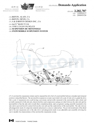
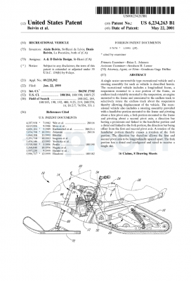
to the suspension system 20. When the suspension system is at rest, the
vertical distance between
a top surface of the rear bumper 4 of the vehicle and the distal end of the
primary pivoting arms
64 is 19.892 inches. However, when the suspension system is active and at its
maximum
flexibility, the primary pivoting arms are in a relatively horizontal position
allowing for a vertical
clearance of at least 11.500 inches from the ground to the top surface of the
rear bumper 4 of the
vehicle. As is further illustrated in shadow lines in Fig. 4, track tension
creates a compression
of the rearward portion of the suspension system. The pulling belts are able
to pull down a front
portion of the chassis so that the rearwardly mounted travel means remain
generally horizontal
and remain in contact with the ground thereby maintaining good traction.
For purposes of completeness, the following is a chart of the angle of
displacement of the
primary pivoting arms 60, and the vertical distance from the distal end of the
primary pivoting
arms 60 to a top horizontal surface of the rear bumper 4 of the particular
land vehicle given in
this example:
An~le of Displacement (degrees Clearance (inches)
18.92 8.392
26.52 12.219
34.43 16.784
When the suspension system 20 is in full extension, the minimum angle of
displacement from
the distal end of the primary pivoting arm is 18.92 degrees, and when the
suspension system is
at rest, the maximum angle of displacement from the distal end of the primary
pivoting arm is
34.43 degrees.
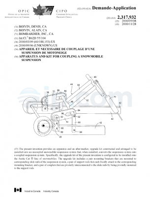
The above description is of a generally centrally mounted rear suspension
system for a
land vehicle, such as a snowmobile. In an alternative embodiment, the
suspension system may
be in the form of a kit separate from the vehicle as a whole. The kit may be
assembled and
attached to a conventional snowmobile and used to modify an already existing
suspension
system.
-19-

CA 02271402 1999-OS-10
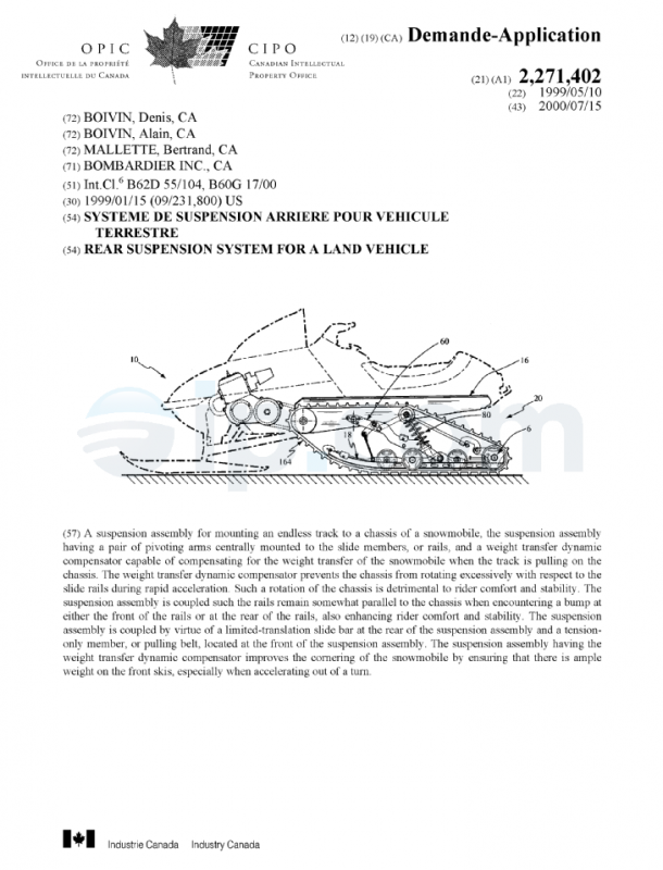
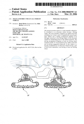
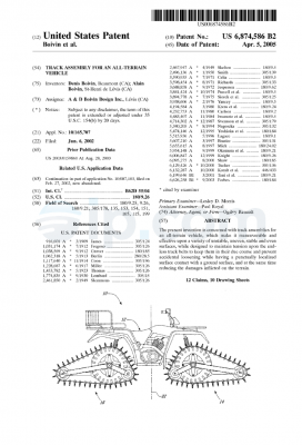
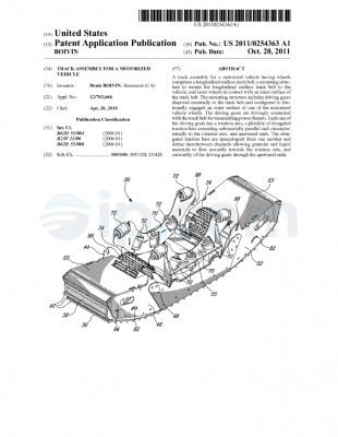
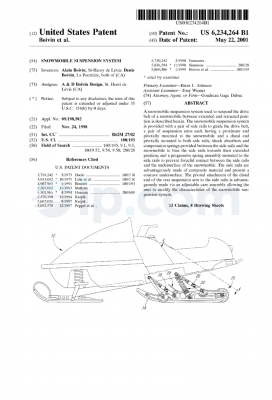
In the most preferred embodiment, a suspension assembly, designated
comprehensively
by the numeral 20, is able to mount an endless track 164 to a chassis 16 of a
snowmobile 10 as
best illustrated in Figures 14 and 15. While the suspension assembly 20 is, in
the most preferred
embodiment, attached to a snowmobile, such a suspension assembly could also be
adapted for
mounting to other types of tracked vehicles.
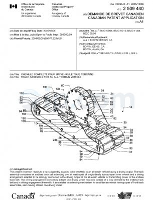
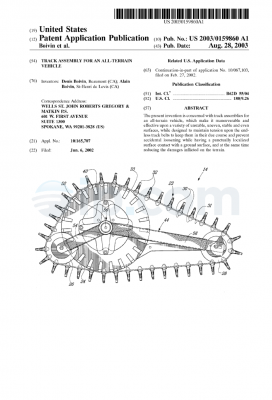
As shown in Figures 16-19, in the most preferred embodiment, the suspension
assembly
20 comprises two substantially parallel and spaced-apart elongated slide
members 18. The slide
members 18 are connected together by at least one transversely mounted bridge
member 70, 78.
The slide members 18 guide the endless track 164 and are commonly referred to
in the art as
“slide rails”. The slide members 18 are typically made of a light, rigid metal
such as aluminum.
The undersides of the slide members 18 are normally covered with a wear-
resistant polymer.
The slide members 18 often have a front portion that is curved upwards to
facilitate the traversing
of rough terrain.
In the most preferred embodiment, the suspension assembly 20 further comprises
two
substantially parallel and elongated pivoting arms 60, each having a first end
portion 64 pivotally
connected to said slide members 18 and a second end portion 62 adapted for
connection to the
chassis 16. The pivoting arms 60 are shaped so as to resist bending and to
minimize the
interference with other components of the suspension assembly 20 when the
suspension assembly
20 is compressed. In the most preferred embodiment, the pivoting arms 60 are
made of a light,
rigid material such as aluminum.
In the most preferred embodiment, the suspension assembly 20 further comprises
a rocker
arm assembly 120, 137 pivotally connected to said pivoting arms 60. The rocker
arm assembly
120, 137 has a first end portion 11 S pivotally connected to a substantially
rigid link 110. The
rocker arm assembly also has a second end portion 135 connected to a tension-
only member 130,
said tension-only member being connected to said slide members 18. The tension-
only member
130 is a linking member capable of withstanding only a tension load (i.e. it
cannot support a
compressive load). Some examples of tension-only members are ropes, cords,
belts and straps.
-20-

CA 02271402 1999-OS-10
In the most preferred embodiment, the suspension assembly 20 further comprises
a
resilient member 80 (also referred to as the primary suspension means). The
resilient member
80 is connected at a first end portion 82 to the chassis 16 and at a second
end portion 84 to the
slide members 18. When compressed, the resilient member 80 urges the slide
members 18 away
from the chassis 16. When the suspension is in static equilibrium, the
resilient force produced
by the resilient member 80 that urges the slide members 18 away from the
chassis 16 is
counterbalanced by the weight of the chassis and vehicle supported above it.
When the
suspension encounters bumps in the terrain, the resilient member 80 absorbs
and dissipates most
of the impact energy.
In the most preferred embodiment, the suspension assembly 20 further comprises
a slide
bar 150. The slide bar 150 has a first end portion 152 connected to the
chassis 16 and a second
end portion 154 slidingly engaged to a holder 170. The holder 170 is pivotally
mounted (at pivot
174) to a rear portion 19 of said slide members 18. The slide bar 150 is
capable of limited
1 S translation relative to said holder 170 by virtue of the washer 159 and
nut 1 SS on the threaded
end 157 of the slide bar 150. The slide bar 150 is thus restricted to move
within the internal gap
of the holder 170. Thus, the slide bar 1 SO limits the displacement of the
slide members 18
relative to the chassis 16.
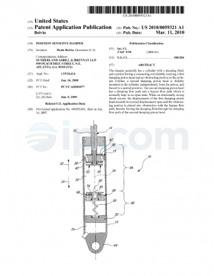
Preferably, the resilient member 80 includes at least one spring 81. The most
common
and logical arrangement is to provide the suspension assembly 20 with two
identical,
symmetrically-disposed springs 81 in order to give the suspension assembly a
balanced and
stable response to impacts. More preferably, the resilient member 80 further
includes a damper
83. The damper 83 is advantageously arranged in tandem with each spring 81 as
illustrated in
Figure 17. The two symmetrical spring-damper units absorb and dissipate the
kinetic energy
imparted to the slide members 18 when the snowmobile 10 encounters a bump. The
quick and
controlled absorption and dissipation of the impact energy by the spring-
damper combination
maximizes comfort and handling. By varying the spring rate, damping ratio, and
geometry of
the shocks, the dynamic response of the suspension can be tailored from a
hard, “sport”
suspension to a softer, “touring” suspension. A suspension can have a “rising
rate” (the
stiffness of the springs increases as they are compressed) or a “falling rate”
(the stiffness of the
-21-

CA 02271402 1999-OS-10
springs is decreased as they are compressed) or a combination thereof (i.e.
the response of the
suspension varies as a function of the position and angle of the shocks).
Preferably, the tension-only member 130 is a pulling belt. The pulling belt is
capable of
limiting the upward motion of the rocker arm assembly 120, 137 away from the
slide members
18. The pulling belt thus restrains the front portion 15 of the chassis 16
during rapid
accelerations when the front portion of the chassis has a tendency to rise.
Preferably, the rocker arm assembly 120, 137 is integral with a tube 75a. The
tube 75a
may be permanently fixed to the rocker arm assembly by welding, soldering or
bonding
(depending on the materials used). In the most preferred embodiment, the tube
75a is welded to
the rocker arm assembly. Rotatable within the tube 75a is a shaft 75, shown in
Figure 16. The
shaft 75 is mounted transversely between the pivoting arms 60 by a threaded
fastener on either
end. The shaft 75 ensures that any tensile force generated by the pulling belt
130 is distributed
equally on both pivoting arms 60. Most preferably, the pulling belt is located
midway between
the pivoting arms to ensure an equal distribution of forces. However, the
pulling belt need not
be located midway in order for the suspension to function properly. The shaft
75 may also serve
as a cross-brace between the pivoting arms 60 to ensure that both pivoting
arms move in unison.
Preferably, the rocker arm assembly 120, 137 further comprises two rocker arms
120 and
137 mounted to the tube 75a in a transversely spaced-apart relation as shown
in Figure 16. The
rocker arms are angled with respect to one another (as seen in the plane
defined normal to the
axis of the tube 75a, i.e. in the plane shown in Figures 17-19). The rocker
arms 120 and 137 are
welded to the tube 75a. As will be shown below, other rocker arm
configurations are also
possible as indeed are other methods of rigid attachment.
In a second variant, instead of two distinct rocker arms, the rocker arm
assembly
comprises a unitary, generally L-shaped rocker arm 137 as shown in Figure 21.
This
arrangement is similar to the previous variant except that the arms of the
rocker are not
transversely spaced-apart. The second variant functions almost identically to
the first variant
shown in Figures 16-19. The generally L-shaped rocker arm 137 is pivotally
mounted to the
-22-

CA 02271402 1999-OS-10
tube 75a and pivotally connected to the rigid link 110 at pivotal end 115. The
generally L-
shaped rocker arm is also connected to the pulling belt 130. If the pulling
belt 130 is again
located midway between the pivoting arms 60, then the rigid link 110 will be
also located
midway between the pivoting arms. To locate the rigid link midway between the
pivoting arms,
the middle idler wheel on the first transverse member 40 would need to be
displaced to allow the
rigid link to attach to the first transverse member 40. Alternatively, the
rigid link could have a
forked end so that the rigid link attaches to the first transverse member 40
at two attachment
points on either side of the middle idler wheel.
In a third variant, the rocker arm assembly comprises a pulley 139 around
which the
pulling belt 130 is partially wrapped as shown in Figure 22. The pulley 139 is
connected to a
rocker arm 120. When the pivoting arms 60 move upwards, the pulley 139 rotates
making the
pulling belt taut. When the pulling belt is taut, the tensile force of the
pulling belt 130 limits the
upward movement of the front portion 15 of the chassis 16.
A fourth variant is illustrated in Figure 23 in which the rocker arm assembly
comprises
a pulley 139 around which the pulling belt 130 is partially wrapped. In the
variant of Figure 23,
the pulling belt is partially wrapped around the rear-facing side of the
pulley 139 as opposed to
the front-facing side of the pulley as was the case in Figure 22. In Figure
23, the rocker arm 120
is oriented toward the front portion 15 of the chassis 16 whereas, in Figure
22, the rocker arm
120 is oriented toward the slide members 18.
A fifth variant is illustrated in Figure 24 in which the rocker arm assembly
comprises a
generally linear rocker arm 120. In Figure 24, the rocker arm 120 is pivotally
connected to the
tube 75a around shaft 75. The pulling belt 130 is connected to one end of the
rocker arm 120.
The rigid link 110 is connected to the rocker arm 120 at the pivotal end 115.
A sixth variant is illustrated in Figure 25 in which the rocker arm assembly
comprises a
generally L-shaped pulley-like member 137 capable of exerting a tensile force
on said pulling
belt 130. The generally L-shaped pulley-like member 137 is pivotally mounted
to the shaft 75
and connected to the rigid link 110 at pivotal end 115. The pulling belt 130
is mounted to the
-23-

CA 02271402 1999-OS-10
front-facing surface of the L-shaped pulley-like member 137. When the L-shaped
pulley-like
member 137 rotates, the pulling belt becomes taut thereby exerting a
restraining force on the
pivoting arms 60 which tends to limit the upward movement of the front portion
15 of the chassis
16.
For any of the foregoing variants, the suspension assembly 20 may further
comprise a
second tension-only member 131 connected at one end to said rocker arm
assembly 120,137 and
connected at a second end to said slide members 18 via a transverse member 78.
The second
tension-only member functions in precisely the same manner as the first
tension-only member
(i.e. the pulling belt 130). The second tension-only member 131 is simply a
backup member that
limits the upward movement of the front 15 of the chassis 16 in case the
pulling belt 130 breaks.
The second tension-only member 131 is preferably a limiting strap made of a
tough, light
material such as nylon or reinforced rubber.
1 S In any of the foregoing variants, the resilient member 80 and the rigid
link 110 may be
connected to a first transverse member 40, the transverse member 40 being
connected to the
chassis 16. The first transverse member 40 is preferably made of steel,
aluminum or an alloy
and is rigid enough not to deflect or deform substantially under the loads
imposed upon it by the
chassis 16, the resilient member 80, the slide bar 150 and the rigid link 110.
Similarly, in any of the foregoing variants, the second end portion 62 of the
pivoting arms
60 may be connected to a second transverse member 50, the second transverse
member being
connected to the chassis 16 at the front portion 15. The transverse member 50
is preferably a
hollow shaft made of steel or aluminum and which is disposed with two flanges
welded thereto.
The flanges are provided with holes for fastening to the pivoting arms 60. The
transverse
member should be rigid enough to withstand all loads imposed on it by the
chassis and pivoting
arms without substantial deformation.
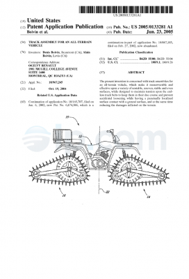
In operation, the suspension assembly 20 functions firstly to absorb and
dissipate impact
energy transmitted to the suspension assembly while traversing rough terrain
and, secondly, to
compensate for the weight transfer induced when the engine is pulling on the
track.
-24-

CA 02271402 1999-OS-10
In the latter case, when the snowmobile 10 undergoes rapid acceleration, the
engine pulls
on the track, thereby putting a portion of the track into tension. This
tensile force creates internal
reactions which cause the rear of the chassis to dip and the front 15 of the
chassis to rise. Thus,
when viewed from the left side as in Figures 17-25, the chassis tends to
rotate in a clockwise
direction. When the front of the chassis rises and the acute angle between the
pivoting arms 60
and the slide members 18 increases, the second transverse member (shaft 50)
rises with respect
to the first transverse member (shaft 40). Since both members 50 and 40 are
fixed to the chassis,
the distance between them necessarily remains the same. However, since the
shaft 75 is rigidly
attached to the pivoting arms 60, the distance between the shaft 75 and the
first transverse
member 40 diminishes. As the shaft 75 nears the first transverse member 40,
the rigid link 110
exerts a force on the rocker arm 120 at the pivotal end 115 causing the rocker
arm 120 and hence
the tube 75a to pivot about the shaft 75 in a clockwise orientation (again as
viewed from the left
side). The clockwise rotation of the tube 75a about the shaft 75 also causes
the rocker arm 137
to rotate about the shaft 75. The rotation of the rocker arm 137 causes the
second end portion
135 to rise with respect to the slide members 18. As the second end portion
135 rises, the pulling
belt 130 becomes taut, as shown in Figure 20, thereby precluding any further
upward movement
of the front portion 15 of the chassis 16. Thus, during rapid accelerations,
when the front
portion 15 of the chassis 16 tends to rise due to track tension, the
suspension assembly
counteracts the weight transfer by restraining the front portion 15 of the
chassis 16 from further
elevation.
When traversing bumpy terrain, the suspension assembly 20 absorbs impacts and
ensures
that the rails (i.e. slide members) remain essentially parallel to the
chassis. In the foregoing
analysis of the suspension’s weight transfer dynamic compensation, the slide
members were
treated as if they remained on the ground at all times and the chassis moved
with respect to the
slide members. When considering the suspension’s response to a bump, the point
of view is
reversed: the chassis can be treated as being somewhat fixed while the rails
move.
A bump acting at the rear of the slide members produces essentially the same
relative
response as the weight transfer dynamic compensation described above. In other
words, the rear
of the slide members moving toward the rear portion of the chassis is
essentially equivalent to
-25-

CA 02271402 1999-OS-10
the rear of the chassis dipping toward the rear of the slide members. The
suspension, being
coupled, will react by lifting the front of the slide members so that the
slide members rise in a
substantially parallel manner. When the bump acts on the rear of the slide
member 18, the slide
members rotate counterclockwise as shown in Figure 33.
This rear bump compresses the resilient members 80 and causes the slide bar
150 to
translate within the holder 170 such that the nut 155 moves toward the surface
176. Due to the
counterclockwise rotation of the slide members 18, the acute angle between the
pivoting arms
60 and the slide members 18 increases until the pulling belt 130 becomes taut.
The slide
members 18 are thus limited from further counterclockwise rotation. The front
and rear of the
suspension are coupled and any further compression in the form of a
counterclockwise rotation
of the suspension necessarily compresses the resilient members 80. The slide
members 18
remain substantially parallel to the chassis once the suspension is coupled.
1 S Another way to visualize the effect of a rear bump is to imagine a bump
propagating
under the slide members moving from the front of the slide members toward the
rear. When the
bump is exactly midway along the slide members, as shown in Figure 32, the
suspension is in
its “ideal posture” because the slide members are instantaneously parallel to
the chassis and to
the ground. Then, when the bump moves toward the rear, the front of the slide
members drop.
This dropping of the front of the slide members amounts to a counterclockwise
rotation which
causes the angle between the pivoting arms 60 and the slide members to
increase until the pulling
belt 130 become taut enough to preclude any further counterclockwise rotation
of the slide
members. The suspension is thus coupled.
A bump acting at the front of the slide members causes the slide members to
rotate
clockwise as shown in Figure 31. As the rear portion 19 of the slide members
drops, the distance
between the pivot 174 (of the holder 170) and the first transverse member 40
diminishes until
the washer 159 and nut 155 abut the holder 170. In other words, the slide bar
slides in the cavity
172 of the holder 170 until the washer 159 and the nut 155 collide with the
inner surface of the
holder. At that point, as shown in Figure 31, the suspension becomes coupled.
The slide
members 18 are no longer able to freely rotate clockwise. Any further attempt
to rotate the slide
-26-

CA 02271402 1999-OS-10
members clockwise is resisted by the resilient members 80. With the slide bar
150 abutting the
holder 170, the suspension is coupled and the rear of the slide members will
then rise with the
front of the slide members. Thus, the slide members remain substantially
parallel to the chassis
when encountering a bump on the front of the slide members.
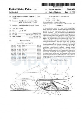
In summation, the rocker arm assembly 120, 137, pulling belt 130 and rigid
link 110
function collectively as a Weight Transfer Dynamic Compensator (“WTDC”). The
WTDC is
essentially a mechanical chain linking the slide members 18 to the chassis 16.
The six variants
described above illustrate that there are numerous ways to implement a WTDC.
In all of the
variants, there is a tension-only member that is activated by a pivotal or
rotational movement
governed by the pivoting arms.
The WTDC compensates dynamically for the weight transfer of the snowmobile
that
arises when the engine is pulling on the track. A snowmobile with a WTDC is
not only more
comfortable to ride during rapid acceleration but it maintains better ground
contact. When the
weight on the front skis is diminished (as a direct result of weight
transfer), the steering capacity
is commensurately reduced. Thus, the WTDC ensures that even though the
snowmobile is
undergoing rapid accelerations, there is still enough weight on the front skis
to permit proper
steering of the snowmobile. This enhances cornering performance since the
snowmobile rider
is able to steer and accelerate concurrently.
Although the present invention has been described in connection with preferred
embodiments thereof, it will be appreciated by those skilled in the art that
additions, deletions,
modifications, and substitutions not specifically described may be made
without departing from
the spirit and scope of the invention as defined in the appended claims and
the scope should not
be limited to the dimensions indicated hereinabove.
-27-

(Source: IFI)

Rear suspension system for a land vehicle – CA 2271402 A1 – IP.com

1. A suspension assembly for mounting an endless track to a chassis of a
snowmobile, said
suspension assembly comprising:
(a) two substantially parallel and spaced-apart elongated slide members
connected
together by at least one transversely mounted bridge member;
(b) two substantially parallel and elongated pivoting arms, each having a
first end
portion pivotally connected to said slide members and a second end portion
adapted for
connection to the chassis;
(c) a rocker arm assembly pivotally connected to said pivoting arms, said
rocker arm
assembly having:
– a first end portion pivotally connected to a substantially rigid link, said
link being
pivotally connected to the chassis;
– a second end portion connected to a tension-only member, said tension-only
member
being connected to said slide members;
(d) a resilient member connected at a first end portion to the chassis and at
a second end
portion to the slide members; and
(e) a slide bar having a first end portion connected to the chassis and a
second end
portion slidingly engaged to a holder, said holder being pivotally mounted to
a rear portion of
said slide members whereby said slide bar is capable of limited translation
relative to said holder
thereby limiting the displacement of said slide members relative to the
chassis.

2. A suspension assembly as defined in claim 1 wherein said resilient member
includes at
least one spring.

3. A suspension assembly as defined in claim 2 wherein said resilient member
further
includes a damper.

4. A suspension assembly as defined in claim 3 wherein said tension-only
member is a
pulling belt.

-28-

5. A suspension assembly as defined in claim 4 wherein said rocker arm
assembly
comprises a shaft mounted transversely between said pivoting arms.

6. A suspension assembly as defined in claim 5 wherein said rocker arm
assembly further
comprises two rocker arms mounted to said shaft in a transversely spaced-apart
relation.

7. A suspension assembly as defined in claim 6 wherein said rocker arms are
angled with
respect to one another in the plane normal to the axis of said shaft.

8. A suspension assembly as defined in claim 5 wherein said rocker arm
assembly further
comprises a unitary, generally L-shaped rocker arm.

9. A suspension assembly as defined in claim 5 wherein said rocker arm
assembly further
comprises a pulley capable of exerting a tensile force on said pulling belt.

10. A suspension assembly as defined in claim 5 wherein said rocker arm
assembly further
comprises a generally linear rocker arm.

11. A suspension assembly as defined in claim 5 wherein said rocker arm
assembly further
comprises a generally L-shaped pulley-like member capable of exerting a
tensile force
on said pulling belt.

12. A suspension assembly as defined in claim 7 further comprising a second
tension-only
member connected at one end to said rocker arm assembly and connected at a
second end
to said slide members, said second tension-only member capable of limiting the
displacement of the pivoting arms with respect to the slide members.

13. A suspension assembly as defined in claim 12 wherein said second tension-
only member
is a limiting strap.

-29-

14. A suspension assembly as defined in claim 13 wherein said resilient member
and said
rigid link are connected to a first transverse member, said first transverse
member being
connected to the chassis.

15. A suspension assembly as defined in claim 14 wherein said second end
portion of said
pivoting arms is connected to a second transverse member, said second
transverse
member being connected to the chassis.

16. A suspension assembly as defined in claim 8 further comprising a second
tension-only
member connected at one end to said rocker arm assembly and connected at a
second end
to said slide members, said second tension-only member capable of limiting the
displacement of the pivoting arms with respect to the slide members.

17. A suspension assembly as defined in claim 16 wherein said second tension-
only member
is a limiting strap.

18. A suspension assembly as defined in claim 17 wherein said resilient member
and said
rigid link are connected to a first transverse member, said first transverse
member being
connected to the chassis.

19. A suspension assembly as defined in claim 18 wherein said second end
portion of said
pivoting arms is connected to a second transverse member, said second
transverse
member being connected to the chassis.

20. A suspension assembly as defined in claim 19 further comprising a second
tension-only
member connected at one end to said rocker arm assembly and connected at a
second end
to said slide members, said limiting strap capable of limiting the
displacement of the
pivoting arms with respect to the slide members.

21. A suspension assembly as defined in claim 20 wherein said second tension-
only member
is a limiting strap.

-30-

22. A suspension assembly as defined in claim 21 wherein said resilient member
and said
rigid link are connected to a first transverse member, said first transverse
member being
connected to the chassis.

23. A suspension assembly as defined in claim 22 wherein said second end
portion of said
pivoting arms is connected to a second transverse member, said second
transverse
member being connected to the chassis.

24. A suspension assembly as defined in claim 10 further comprising a second
tension-only
member connected at one end to said rocker arm assembly and connected at a
second end
to said slide members, said second tension-only member capable of limiting the
displacement of the pivoting arms with respect to the slide members.

25. A suspension assembly as defined in claim 24 wherein said second tension-
only member
is a limiting strap.

26. A suspension assembly as defined in claim 25 wherein said resilient member
and said
rigid link are connected to a first transverse member, said first transverse
member being
connected to the chassis.

27. A suspension assembly as defined in claim 26 wherein said second end
portion of said
pivoting arms is connected to a second transverse member, said second
transverse
member being connected to the chassis.

28. A suspension assembly as defined in claim 11 further comprising a second
tension-only
member connected at one end to said rocker arm assembly and connected at a
second end
to said slide members, said second tension-only member capable of limiting the
displacement of the pivoting arms with respect to the slide members.

29. A suspension assembly as defined in claim 28 wherein said second tension-
only member

-31-

is a limiting strap.

30. A suspension assembly as defined in claim 29 wherein said resilient member
and said
rigid link are connected to a first transverse member, said first transverse
member being
connected to the chassis.

31. A suspension assembly as defined in claim 30 wherein said second end
portion of said
pivoting arms is connected to a second transverse member, said second
transverse
member being connected to the chassis.

32. A snowmobile comprising:
– a chassis;
– an engine mounted on said chassis;
– an engine cowling enveloping said engine and supporting a windshield;
– a seat mounted on said chassis;
– a steering member mounted on said chassis and connected to a pair of
steerable front
skis;
-a front suspension mounted on said chassis and connected to said front skis;
– a ground-engaging track connected to said engine via a drive sprocket;
– a suspension assembly as defined in any one of the preceding claims for
mounting said
track to said chassis.

33. A suspension assembly for mounting an endless track to a chassis of a
snowmobile, said
suspension assembly comprising:
(a) two substantially parallel and spaced-apart elongated slide members
connected
together by at least one transversely mounted bridge member;
(b) a substantially parallel and elongated pivoting arm having a first end
portion
pivotally connected to one of said bridge members and a second end portion
adapted for
connection to the chassis;
(c) a rocker arm assembly pivotally connected to said pivoting arm, said
rocker arm
assembly having:

-32-

– a first end portion pivotally connected to a substantially rigid link, said
link being
pivotally connected to the chassis;
– a second end portion connected to a tension-only member, said tension-only
member
being connected to said slide members;
(d) a resilient member connected at a first end portion to the chassis and at
a second end
portion to the slide members; and
(e) a slide bar having a first end portion connected to the chassis and a
second end
portion slidingly engaged to a holder, said holder being pivotally mounted to
a rear portion of
said slide members whereby said slide bar is capable of limited translation
relative to said holder
thereby limiting the displacement of said slide members relative to the
chassis.

34. A suspension assembly for mounting an endless track to a chassis of a
snowmobile, said
suspension assembly comprising:
(a) two substantially parallel and spaced-apart elongated slide members
connected
together by at least one transversely mounted bridge member;
(b) two substantially parallel and elongated pivoting arms, each having a
first end
portion pivotally connected to said slide members and a second end portion
adapted for
connection to the chassis;
(c) a rocker arm assembly pivotally connected to said pivoting arms, said
rocker arm
assembly having:
– a first end portion pivotally connected to a substantially rigid link, said
link being
pivotally connected to the chassis;
– a second end portion connected to a tension-only member, said tension-only
member
being connected to said slide members; and
(d) a resilient member connected at a first end portion to the chassis and at
a second end
portion to the slide members.

35. A suspension assembly for mounting an endless track to a chassis of a
snowmobile, said
suspension assembly comprising:
(a) a pair of rail-like slide members;
(b) a pair of pivoting anus pivotally connecting said slide members to said
chassis;

-33-

(c) a rocker arm assembly pivotally connected to said pivoting arms, said
rocker arm
assembly being pivotally connected at a first end to a substantially rigid
link, said link being
pivotally connected to the chassis; said rocker arm assembly being connected
at its opposite end
to a tension-only member, said tension-only member being connected to said
slide members;
(d) means for resiliently connecting said chassis to said slide members; and
(e) a displacement-limiting means having a first end portion connected to the
chassis
and a second end portion connected to a rear portion of said slide members for
limiting the
displacement of said slide members relative to the chassis.

-34-

(Source: IFI)