Français
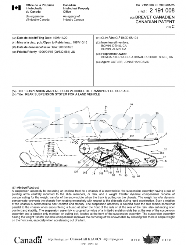
Canadian Application Publication
Title (French)
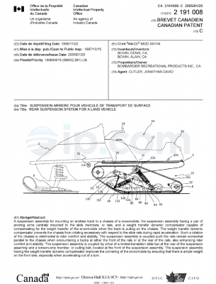
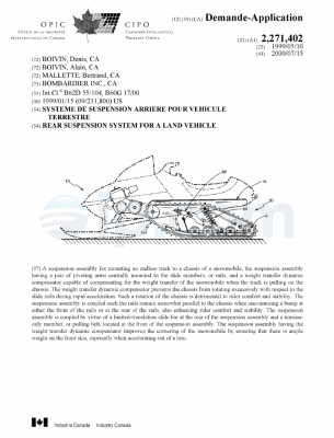
Suspension arriere pour vehicule de transport de surface
Abstract (English)
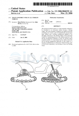
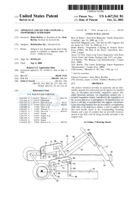
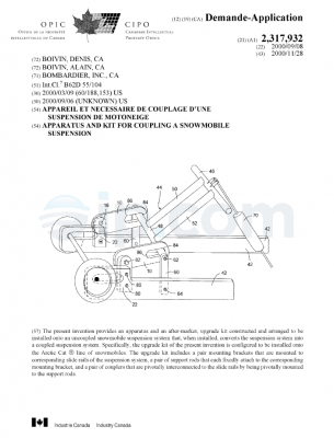
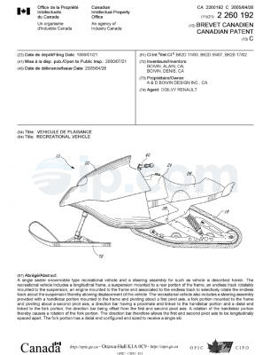
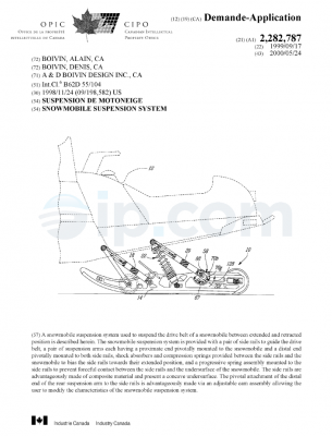
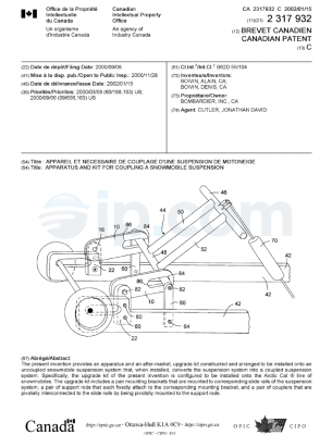
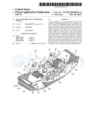
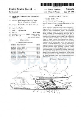
A rear suspension system for a land vehicle comprising a single generally centrally mounted structure in a middle portion of the rear suspension system. The suspension system comprises a pair of inclined primary suspension means, and a pair of inclined primary oscillating arms for pivotally connected to a pair of laterally spaced longitudinal slides at an underside area of the chassis of the land vehicle. Each of the primary oscillating arms comprise a distal end, which are further coupled to a horizontal bar adjacent a distal end of the primary suspension means, such as a shock absorber, and a proximal end which are individually mounted a horizontal bar adjacent a front end of the primary suspension means at an underside portion of the chassis. The suspension system further comprises a Weight Transfer Dynamic Compensator for raising a front tip portion of the longitudinal slides each time there is a transfer of weight in the vehicle. The Weight Transfer Dynamic Compensator is beneficial during acceleration and cornering of the vehicle by allowing the front end of the vehicle to remain close to the ground, thereby providing improved traction and control of the vehicle.
Inventors
BOIVIN, DENIS [+1]
BOIVIN, ALAIN
Applicants
BOMBARDIER INC.
Priority
US 632,581 A 15-Apr-1996
Classifications
International (2006.01): B62D 55/108; B62M 27/02
International: B62D 55/104
Cooperative (2013.01.01): B62M 27/02; B62M 2027/026; B62D 55/108
European: B62D 55/108; B62M 27/02
Language of Filing
English
Also Published As
|
CA 2191008 C |
patent |
Jan-2005 |
||
|
US 5860486 |
patent |
Jan-1999 |