Canadian Application Publication
Title (French)
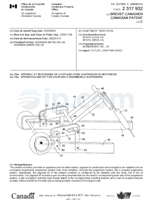
Chenille pour vehicules nivaux
Abstract (English)
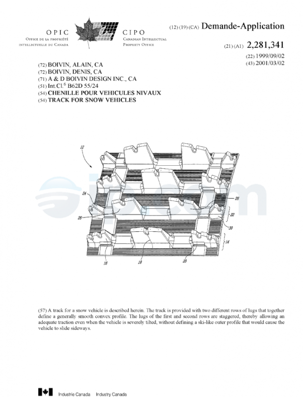
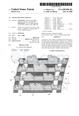
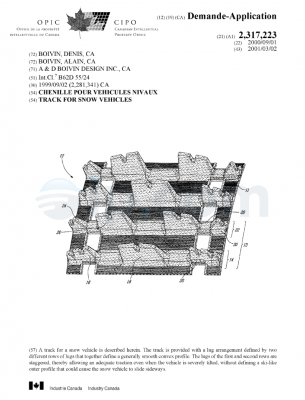
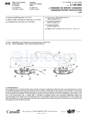
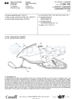
A track for a snow vehicle is described herein. The track is provided with two different rows of lugs that together define a generally smooth convex profile. The lugs of the first and second rows are staggered, thereby allowing an adequate traction even when the vehicle is severely tilted, without defining a ski-like outer profile that would cause the vehicle to slide sideways.
Inventors
BOIVIN, ALAIN [+1]
ST-HENRI DE LÉVIS, Q1, CA
Applicants
A & D BOIVIN DESIGN INC.
LÉVIS, Q1, CA
Assignees
A & D BOIVIN DESIGN INC. [+2]
LÉVIS, Q1, CA
Priority
CA 2281341 A 02-Sep-1999
Classifications
International (2006.01): B62D 55/24; B62D 55/27
International: B62D 55/24
Cooperative (2013.01.01): B62D 55/24; B62D 55/27
European: B62D 55/27; B62D 55/24
Language of Filing
English
Attorney, Agent or Firm
OGILVY RENAULT LLP/S.E.N.C.R.L.,S.R.L.
CA
CA 02281341 1999-09-02
1
TITLE OF THE INVENTION
Track for snow vehicles
FIELD OF THE INVENTION
The present invention relates to snow vehicles. More
specifically, the present invention is concerned with a track for a snow
vehicle.
BACKGROUND OF THE INVENTION
Endless tracks are well known in the art of snow
vehicles since they are particularly efficient at propelling a vehicle on soft
and hard snow.
Conventional snowmobiles having relatively wide tracks
are also well known and many designs of tracks have been designed for
them over the years. These conventional snowmobiles usually have a
relatively long seat that allow the snowmobiles to be ridden by two
people: a driver and a passenger. This, combined with the fact that
snowmobiles are relatively wide and provided with a heavy gasoline
powered engine, make them relatively bulky recreational vehicles.
A new type of snow vehicle has been proposed to
overcome the bulkiness of the conventional snowmobile. It consists of a
CA 02281341 1999-09-02
2
relatively narrow single seater snowmobile type recreational vehicle
provided with an equally narrow track.
Such a recreational vehicle is described, for example,
in United States Patent No. 4,613,006, entitled « ENDLESS BELT DRIVEN
CYCLE », issued on September 23, 1986 to Alvin MOSS et al.. Moss
vehicle is basically a motorcycle where the front wheel has been replaced
with a directing ski and the rear wheel has been replaced with a drive
arrangement provided with a track.
A major drawback of the track described by Moss is the
side to side continuity of the cleats. Indeed this side to side continuity
forces Moss to add outwardly projecting ribs extending transversely of the
cleats to counteract the lateral slippage of the drive track. Indeed, since
the convex cleats are continuous from one side to the other of the track,
they act as skis when the vehicle is banked for a turn, thereby decreasing
the stability of the vehicle.
pBJECTS F THE INVENTION
An object of the present invention is therefore to provide
an improved endless track for snow vehicles.
Other objects, advantages and features of the present
invention will become more apparent upon reading of the following non
restrictive description of preferred embodiments thereof, given by way of
example only with reference to the accompanying drawings.
CA 02281341 1999-09-02
3
BRIEF DESCRIPTION OF THE DRAWINGS
In the appended drawings:
Figure 1 is a side elevational view of a recreational snow
vehicle provided with a track according to an embodiment of the present
invention;
Figure 2 is a top plan view of the recreational snow
vehicle of Figure 1;
Figure 3 is a perspective view of a track according to an
embodiment of the present invention;
Figure 4 is a top plan view of a portion of the track of
Figure 3;
Figure 5 is a sectional view taken along line 5-5 of
Figure 4, illustrating two adjacent rows of lugs;
Figure 6 is a sectional view similar to Figure 5 but
illustrating only one of the two different rows of lugs; and
Figure 7 is a sectional view similar to Figure 5 but
illustrating only the other of the two different rows of lugs.
CA 02281341 1999-09-02
4
DESCRIPTION OF THE PREFERRED EMBODIMENT
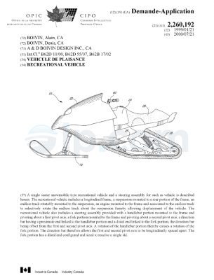
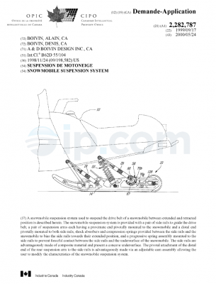
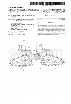
Figures 1 and 2 of the appended drawings illustrate a
recreational snow vehicle 10 provided with an endless track 12 according
to an embodiment of the present invention. As can be better seen from
Figure 2, the endless track 12 is relatively narrow, thereby allowing the
vehicle 12 to be severely tilted during turns.
As will be understood by the following description, the
track 12 is designed to give a good traction even when the vehicle 10 is
tilted laterally, while preventing lateral slippage of the track onto the
ground.
It is to be noted that the general features of snow
vehicles and of the endless tracks used to propel snow vehicles are
believed well known to one skilled in the art and will therefore not be
discussed herein.
Turning now to Figures 3-5 of the appended drawings,
the endless track 12 will be described.
As can be seen from Figure 5, the overall profile of the
track 12, from one side to the other, is generally convex. However, to
overcome the above-noted drawback of the prior art, the convex profile
of the track 12 is created by two successive rows of lugs arranged in a
staggered relationship, as illustrated in Figures 3 and 4.
CA 02281341 1999-09-02
A first row 14 contains three lugs 16, 18 and 20 and a
second row 22 containing four lugs 24, 26, 28 and 30. These lugs are
symmetrical about a longitudinal axis 32 as will be described hereinbelow.
5 Lug 16 of the first row 14 includes three ground
contacting surfaces 34, 36 and 38 separated by two indentations 40 and
42. The shape of lug 16 is such that the ground contacting surfaces 34,
36 and 38 are convex.
Lug 18 is centered about longitudinal axis 32 and
includes two ground contacting surfaces 44 and 46, separated by an
indentation 48. The ground contacting surfaces 44 and 46 are
symmetrical about the longitudinal axis 32 and are convex.
Lug 20 is a mirror image of lug 16 about the longitudinal
axis 32.
In the second row 22, lug 24 includes two ground
contacting surfaces 50 and 52, separated by an indentation 54, and are
slightly convex.
Lug 26 includes two ground contacting surfaces 56 and
58 separated by an indentation 60. As is apparent from Figure 5, the
ground contacting surfaces 56 and 58 are convex.
Finally, lugs 28 and 30 are respectively mirror images
of lugs 26 and 24 with respect to the longitudinal axis 32.
CA 02281341 1999-09-02
6
Of course, the rows 14 and 22 are repeated alternatively
onto the entire external surface of the track 12.
As it is apparent from Figure 5, the ground contacting
surfaces of symmetrical lugs 24 and 30 are not aligned with the outer
surfaces of the outer lugs to form a continuous profile. Indeed, the
ground contacting surtaces of lugs 24 and 30 are more angled and
exceed the convex profile defined by the other lugs. This configuration
of the outer lugs is advantageous since it further prevents the vehicle to
tip over during sharp turns at high speed when the vehicle 10 is severely
tilted.
Turning now briefly to Figures 6 and 7 of the appended
drawings, another lateral slippage preventing feature will be described.
These figures illustrate the angular relationship between the ground
contacting surfaces, in contact with the ground when the vehicle is tilted
laterally, and the side of the corresponding lugs. Since these angles are
90 degrees, the friction between the side of the lugs and the ground
prevent the vehicle to slide laterally. Furthermore, as will be understood
by the different ground representing lines of these figures, the vehicle
provided with a track 12 is stable at many tilt angles. It is therefore an
advantage to design a track 12 where the ground contacting surfaces at
various angles as illustrated and described herein.
It is to be noted that each ground contacting surface
may be provided with a metallic insert, usually in the form of a fastener
(not shown), fixedly mounted to lugs ground engaging surfaces to
CA 02281341 1999-09-02
7
increase the friction between the track 12 and the ground in certain
conditions.
One of ordinary skills in the art will readily understand
that the track 12, when mounted to a snow vehicle, has the advantage of
providing an adequate traction even when the vehicle is severely tilted,
without defining a ski-like outer profile that could cause the vehicle to
slide sideways.
It is finally to be noted that the number of different rows,
the number of lugs on each row and the number of ground engaging
surfaces on each lug could be different from the above description without
departing from the spirit and nature of the present invention.
Although the present invention has been described
hereinabove by way of preferred embodiments thereof, it can be modified,
without departing from the spirit and nature of the subject invention as
defined in the appended claims.
WHAT IS CLAIMED IS:
1. A track for snow vehicle comprising:
an endless belt provided with an external surface and
defining a longitudinal axis;
a first row of lugs having at least two first lugs mounted
to said outer surface of said endless belt;
a second row of lugs having at least two second lugs,
said second row of lugs being so mounted to said external surface of said
endless belt as to be longitudinally spaced apart from said first row of
lugs;
wherein said first lugs and said second lugs are staggered and define a
generally smooth convex outer surface.

 English